Timing control system and method for non-salient pole permanent magnet synchronous motor

A technology of permanent magnet synchronous motor and control system, applied in control system, single motor speed/torque control, vector control system, etc., can solve problems such as increasing the hardware cost of drive control system

Active Publication Date: 2009-12-30
北京和利时电机技术有限公司
View PDF0 Cites 22 Cited by
  • Summary
  • Abstract
  • Description
  • Claims
  • Application Information

AI Technical Summary

Problems solved by technology

In short, this control strategy must require motor current measurement feedback, that is, corresponding current

Method used


Image

  • Timing control system and method for non-salient pole permanent magnet synchronous motor
  • Timing control system and method for non-salient pole permanent magnet synchronous motor
  • Timing control system and method for non-salient pole permanent magnet synchronous motor

Examples


Embodiment 1

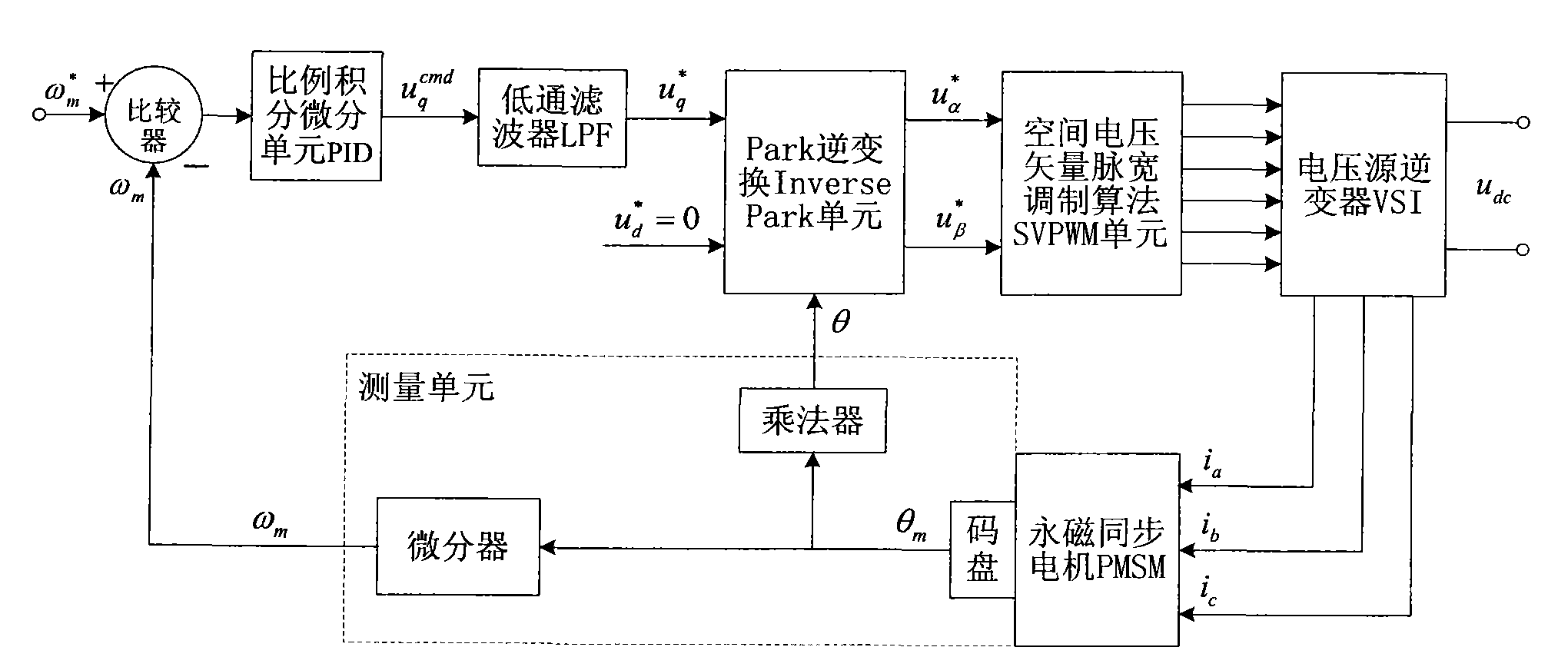
[0085] Embodiment 1, a speed regulation control system of a hidden pole type permanent magnet synchronous motor, such as figure 1 As shown, it includes: proportional integral differential unit PID, Park inverse transform Inverse Park unit, space voltage vector pulse width modulation algorithm SVPWM unit, voltage source inverter VSI, comparator, and measurement unit.

[0086] The measuring unit is used to measure the electrical angle position θ of the rotor of the hidden pole permanent magnet synchronous motor and the mechanical speed ω of the motor m .

[0087] In this embodiment, the measuring unit may include:

[0088] Position measurer, multiplier and differentiator.

[0089] The position measuring device is used to measure the mechanical angular position θ of the rotor m , respectively sent to the multiplier and differentiator; in this embodiment, the position measuring device can be, but not limited to, a code disc installed on the motor shaft end of the hidden pole pe...

Embodiment 2

[0107] Embodiment 2, a speed regulation control method of a hidden pole permanent magnet synchronous motor, comprising:

[0108] Measure the electrical angle position θ of the rotor of the hidden pole permanent magnet synchronous motor and the mechanical speed ω of the motor m ;

[0109] Get the preset target speed ω m * and ω m the difference;

[0110] Perform proportional, integral, and differential operations on the difference to obtain the q-axis voltage component command value u q * ;

[0111] According to θ for u d * and the u q * Perform PARK inverse transformation to obtain the voltage vector u on the stationary coordinate system α * and u β * ; Among them, the u d * is 0;

[0112] According to the voltage vector u α * and u β * , using the space voltage vector pulse width modulation algorithm to generate the pulse width signal of the power device;

[0113] Generate three-phase winding current i according to the pulse width signal of the power dev...


PUM

PropertyMeasurementUnit
Resistanceaaaaaaaaaa
Inductanceaaaaaaaaaa
Damping coefficientaaaaaaaaaa

Abstract

The invention discloses a timing control system and a method for a non-salient pole permanent magnet synchronous motor. The method comprises the following steps: the electrical angle position theta and the mechanical rotational speed omegam of a motor of a non-salient pole permanent magnet synchronous motor rotor are measured; the difference of a preset target rotational speed omegam<*> and omegam is obtained; the difference is performed with scale, integration and differential operation to obtain component instruction value uq<*> of q shaft voltage; voltage vectors ualpha<*> and ubeta<*> on a static coordinate system can be obtained by PARK inverse transformation of ud<*> and uq<*> by theta, wherein, ud<*> is zero; according to ualpha<*> and ubeta<*> of the voltage vector, a power device pulse-width signal can be generated by a space vector pulse width modulation (SVPWM) algorithm; according to the power device pulse-width signal, three-phase winding current is generated and is sent to the non-salient pole permanent magnet synchronous motor. The invention can realize speed loop no-current sensor vector control of the non-salient pole permanent magnet synchronous motor and lower hardware cost for timing.

Description

technical field [0001] The invention relates to the field of control systems, in particular to a speed regulation control system and method for a hidden pole permanent magnet synchronous motor. Background technique [0002] With the rapid development of rare earth permanent magnet materials, power electronics technology and motor control theory, permanent magnet synchronous motor (PMSM) has the advantages of high torque / inertia ratio, high power density, high efficiency, firmness and good maintainability. , has been increasingly widely used in textiles, chemical fibers, numerical control machine tools, industrial robots, aerospace and other fields. [0003] According to the structure of the permanent magnet synchronous motor, the permanent magnet synchronous motor is divided into two types: salient pole type and hidden pole type. In industrial applications, most permanent magnet synchronous motors are hidden pole motors. When the sine wave current control scheme is used to...

Claims


Application Information

Patent Timeline
IPC IPC(8): H02P6/08H02P21/00H02P27/06H02P21/18
Inventor 韩利何震球刘春燕夏燕兰
Owner 北京和利时电机技术有限公司
Why Eureka
Try Eureka