Compensation control circuit of direct current motor

A DC motor, compensation control technology, applied in the direction of DC motor speed/torque control, control system, electrical components, etc., can solve the problems of large switching power consumption, complex circuits, and low accuracy of speed signals

Inactive Publication Date: 2009-12-30
漳州维德焊接技术开发有限公司
View PDF0 Cites 16 Cited by
  • Summary
  • Abstract
  • Description
  • Claims
  • Application Information

AI Technical Summary

Problems solved by technology

The traditional speed measurement circuit requires an external physical sensor to measure the motor speed, and the output signal of the sensor needs to be demodulated and processed by a filter circuit to obtain a usable speed signal. The circuit is complex, many components are required, the cost is high, and the speed signal is not accurate. high
The tr...

Method used


Image

  • Compensation control circuit of direct current motor
  • Compensation control circuit of direct current motor
  • Compensation control circuit of direct current motor

Examples


Embodiment Construction

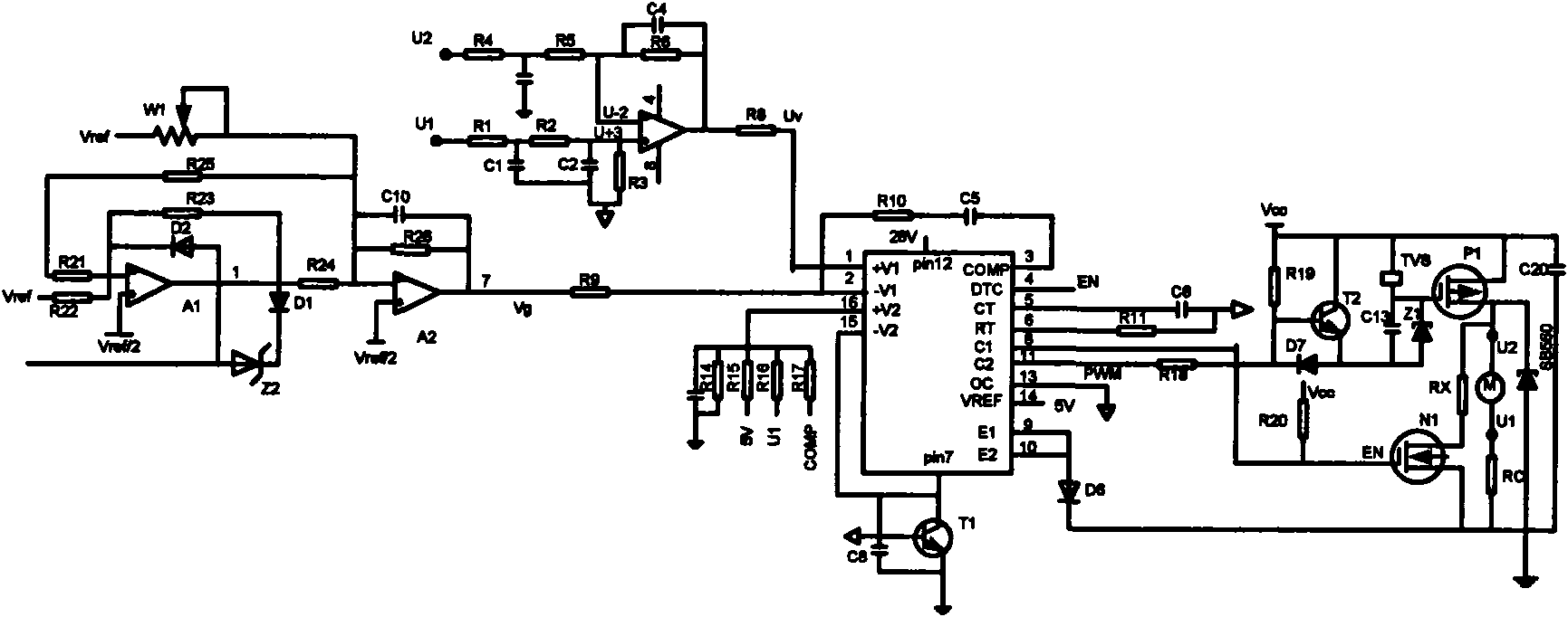
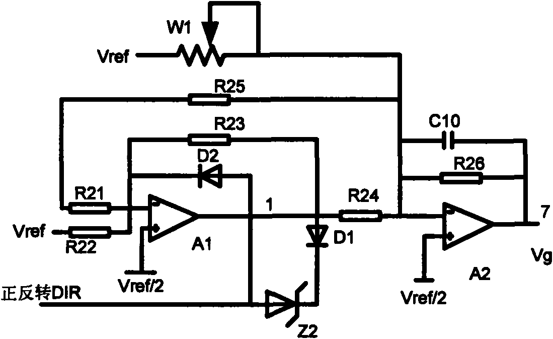
[0026] Please check figure 1 , a DC motor compensation control circuit, which includes a speed measurement circuit, a speed command closed-loop speed regulation circuit and a drive buffer braking circuit. The speed command closed-loop speed regulation circuit includes a speed command conditioning circuit and a speed command control circuit.

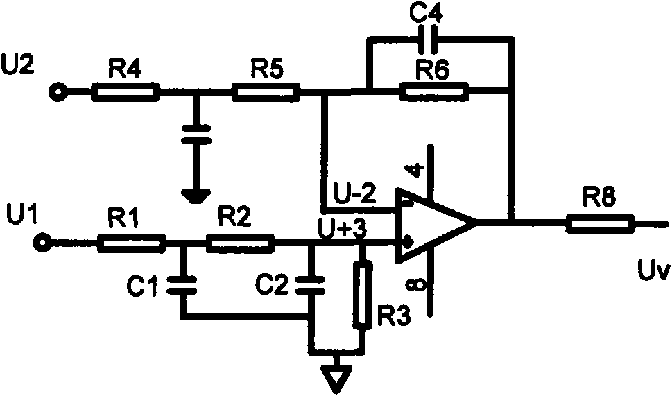
[0027] For the tachometer circuit, please refer to the figure 2 , which includes a first operational amplifier, resistors R1, 2, 3, 4, 5, 6, 8, and capacitors C1, 2, 4. The first operational amplifier collects the ground voltage signals U1 and U2 of the two terminals of the DC motor, and generates a speed test signal Uv. The R1, 2, 3, 4, 5, 6, 8, C1, 2, 4 form a smoothing circuit for smoothing the dynamic characteristics of the first operational amplifier. The working principle of the speed measuring circuit is:

[0028] According to the armature equation of a DC motor:

[0029] E=K a no

[0030] U = ...


PUM


Abstract

The invention discloses a compensation control circuit of a direct current motor, comprising a speed-measuring circuit, a speed instruction conditioning circuit, a speed instruction control circuit and a driving buffering brake circuit. The speed-measuring circuit acquires signals U1 and U2 of voltage to ground of two ends of the direct current motor, and generates a speed-measuring signal Uv. The speed instruction conditioning circuit rectifies the voltage of the speed instruction signal into unipolar level, outputs a control signal of positive and negative rotation of the motor and biased-amplifying the rectified speed instruction signal into a speed instruction signal Vg conforming the range specification of the speed-measuring signal Uv. The speed instruction control circuit comprises an error amplifier and a proportional integral circuit; the error amplifier amplifies error comparison between the speed-measuring signal Uv and the speed instruction signal Vg, and generates a pulse signal for controlling a semiconductor switch device; and the proportional integral circuit controls the error amplifier. The semiconductor switch device of the driving buffering brake circuit is controlled by the pulse signal and is used for driving buffering brake direct current motor.

Description

technical field [0001] The invention relates to a DC motor compensation control circuit. Background technique [0002] The DC motor compensation control circuit generally includes a speed measuring circuit, a speed command speed regulating circuit and a driving buffer braking circuit. The traditional speed measurement circuit requires an external physical sensor to measure the motor speed, and the output signal of the sensor needs to be demodulated and processed by a filter circuit to obtain a usable speed signal. The circuit is complex, many components are required, the cost is high, and the speed signal is not accurate. high. The traditional speed command speed control circuit adopts open-loop PWM circuit, the circuit is complicated, many components are required, the cost is high, and there is static error in speed control. The traditional drive buffer brake circuit does not use semiconductor switches, the switching speed is slow, close to us, and the switching power con...

Claims


Application Information

Patent Timeline
IPC IPC(8): H02P7/00H02P7/285
Inventor 吴世德曾维尔
Owner 漳州维德焊接技术开发有限公司
Why Eureka
Try Eureka