Compensation control circuit of direct current motor
A DC motor, compensation control technology, applied in the direction of DC motor speed/torque control, control system, electrical components, etc., can solve the problems of low accuracy of speed signal, static error of speed control, large switching power consumption, etc.
- Summary
- Abstract
- Description
- Claims
- Application Information
AI Technical Summary
Problems solved by technology
Method used
Image
Examples
Embodiment Construction
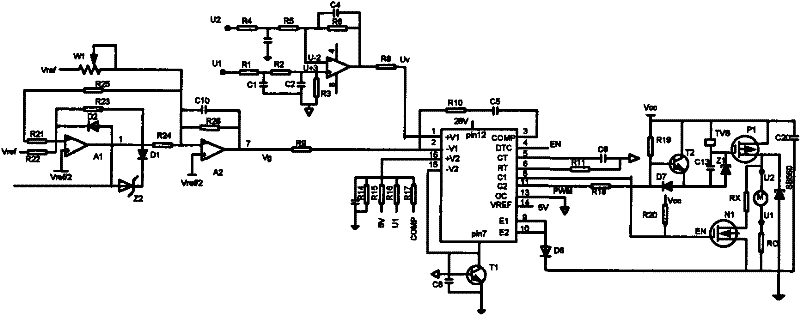
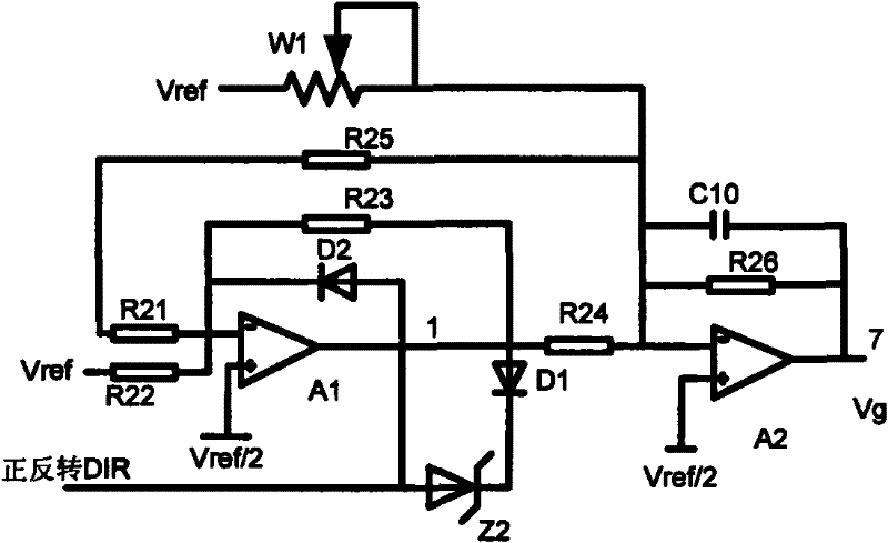
[0026] Please check figure 1 , a DC motor compensation control circuit, which includes a speed measurement circuit, a speed command closed-loop speed regulation circuit and a drive buffer braking circuit. The speed command closed-loop speed regulation circuit includes a speed command conditioning circuit and a speed command control circuit.
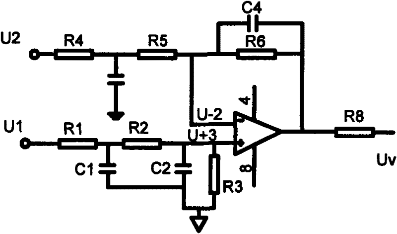
[0027] For the tachometer circuit, please refer to the figure 2 , which includes a first operational amplifier, resistors R1, 2, 3, 4, 5, 6, 8, and capacitors C1, 2, 4. The first operational amplifier collects the ground voltage signals U1 and U2 of the two terminals of the DC motor, and generates a speed test signal Uv. The R1, 2, 3, 4, 5, 6, 8, C1, 2, 4 form a smoothing circuit for smoothing the dynamic characteristics of the first operational amplifier. The working principle of the speed measuring circuit is:
[0028] According to the armature equation of a DC motor:
[0029] E=K a no
[0030] U = ...
PUM
 Abstract
Description
Claims
Application Information
 - R&D
- Intellectual Property
- Life Sciences
- Materials
- Tech Scout
- Unparalleled Data Quality
- Higher Quality Content
- 60% Fewer Hallucinations
Browse by: Latest US Patents, China's latest patents, Technical Efficacy Thesaurus, Application Domain, Technology Topic, Popular Technical Reports.
© 2025 PatSnap. All rights reserved.Legal|Privacy policy|Modern Slavery Act Transparency Statement|Sitemap|About US| Contact US: help@patsnap.com


