
Biomass vaporizing combustion coupled type cyclone boiler

A coupled biomass technology, which is applied to combustion equipment, combined combustion mitigation, and solid fuel combustion, can solve problems such as easy slagging, low thermal efficiency, and high tar content, and achieve improved conversion efficiency, stable operation, and reduced coal consumption. The effect of the possibility of slag

Inactive Publication Date: 2010-01-13
辽宁玺丰新能源科技有限公司
View PDF8 Cites 30 Cited by
  • Summary
  • Abstract
  • Description
  • Claims
  • Application Information

AI Technical Summary

Problems solved by technology

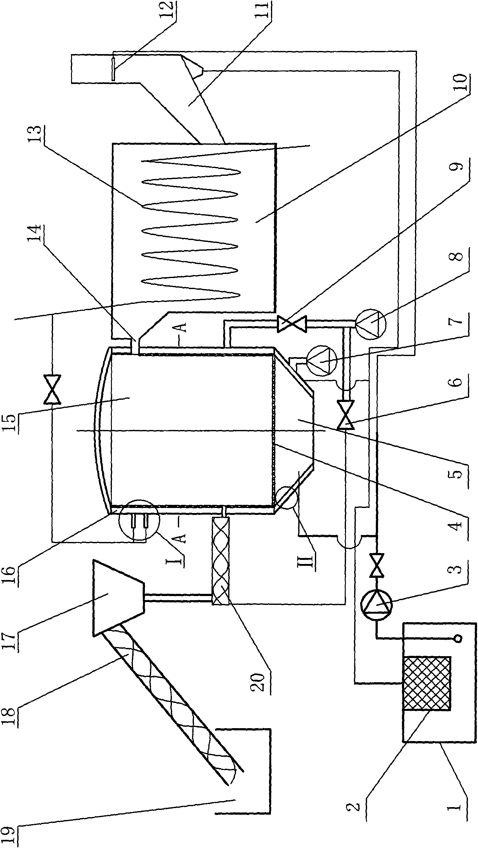
[0005] The purpose of the present invention is to provide a biomass gasification combustion coupled cyclone boiler, which solves the problems of low thermal efficiency, high tar content in the gasification gas, and easy slagging on the high-temperature heating surface of the existing biomass boilers. The design is reasonable, the operation is stable, the effect of heat transfer and fuel gasification is enhanced, the conversion efficiency of biomass energy and the calorific value of the gasification products of biomass fuel can be improved, and the biomass fuel can be fully burned, which saves energy and improves the thermal efficiency of the boiler. , and environmentally friendly, reducing environmental pollution, and can also use the collected biomass ash for waste utilization

Method used


Image

  • Biomass vaporizing combustion coupled type cyclone boiler
  • Biomass vaporizing combustion coupled type cyclone boiler
  • Biomass vaporizing combustion coupled type cyclone boiler

Examples


Embodiment Construction

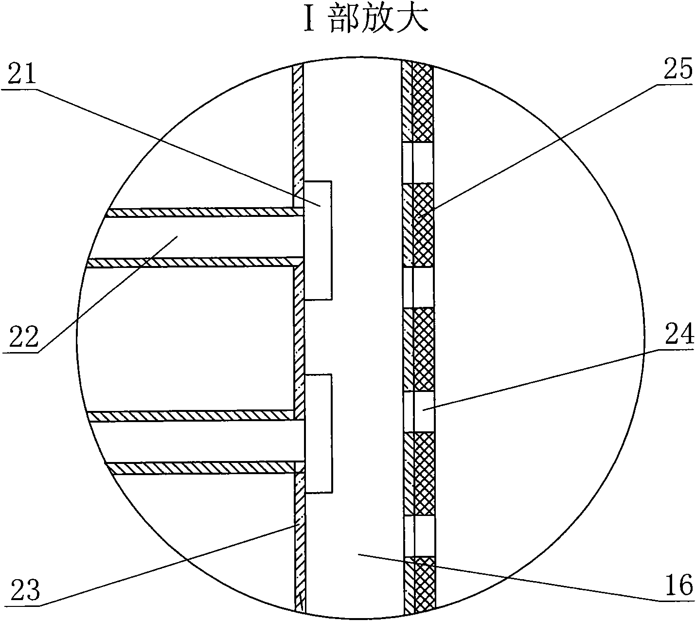
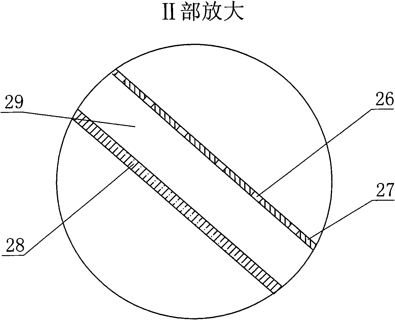
[0018] according to Figure 1~5 The specific structure of the present invention will be described in detail. The biomass gasification combustion coupled cyclone boiler includes a jacketed furnace body with an ash chamber 5, a fire grate 4 and a gasification combustion chamber 15 and a complete combustion chamber 10 with a built-in heat exchanger 13 connected by a connecting pipe 14 The furnace body jacket 16 composed of the inner furnace wall 25 and the outer furnace wall 23 of the common structure of the boiler and the atomizing nozzle 21 communicated with the water inlet pipe 22 arranged inside the outer furnace wall 23, and the inner furnace wall 25 and the gas outlet The steam atomization device formed by the secondary air connected to the chemical combustion chamber 15 and the water vapor tangential spray hole 24 is composed of a raw material bin 19, a large screw feeder 18, a hopper 17 and a small screw feeder 20 arranged below it. The feeding device composed of the pri...


PUM


Abstract

The invention relates to a biomass vaporizing combustion coupled type cyclone boiler, solving the problems of low thermal efficiency, high tar content in vaporizing gas, easy scorification of a high-temperature heating surface and the like existing in the current biomass boiler, and comprising a jacketed type boiler body and a feeding device thereof, a primary air fan, a secondary air fan, a water circulating pump, an ash slurry pond and a flue water fog deduster. The invention has the technical points that the secondary air fan is connected with the jacket of the boiler body, and an atomizing nozzle is arranged on the inner side of an outer boiler wall; secondary air and water vapour tangential jet holes are distributed on the circumference of an inner boiler wall; one end of a small spiral feeder of the feeding device is connected with the inner cavity of a vaporizing combustion chamber, and the other end is connected with the secondary air fan by a feeding air valve; the vaporizing combustion chamber and a complete combustion chamber are communicated. The invention has reasonable structure design and stable operation and strengthens effects of heat transfer and fuel vaporization, which can increase the transformation efficiency of biomass energy and heat values of biomass fuel vaporizing products, and thus, the biomass fuel is completely and sufficiently burnt, thereby saving energy, increasing the heat efficiency of the boiler, protecting environment and reducing environmental pollution.

Description

technical field [0001] The invention relates to a gasification combustion boiler for burning powdery biomass, especially a two-stage reactor with a gasification combustion chamber of a uniquely designed steam atomization device and a complete combustion chamber connected thereto, and A biomass gasification combustion coupled cyclone boiler that improves the conversion efficiency of biomass energy. Background technique [0002] As we all know, biomass energy has been used by humans for a long time, but due to the low energy density of biomass energy, its application efficiency is very low. Therefore, it has not been widely used in daily life and industrial production. With the shortage of energy and the deterioration of the environment, people pay more attention to the application research of biomass energy. The fuel used in general biomass fuel boilers is biomass pellets. In this way, the processing cost of processing straw into biomass pellets can be avoided, the bulk de...

Claims


Application Information

Patent Timeline
IPC IPC(8): F23B10/00C10J3/58C10J3/74F23B10/02
CPCY02E20/18Y02P20/10
Inventor 靖洪铭李柄熙黄东升李洪涛靖海宽黄奎聂彦彬刘子豪
Owner 辽宁玺丰新能源科技有限公司
Learn More