Improved magnesium method flue gas desulphurization technique
What is AI technical title?
AI technical title is built by PatSnap AI team. It summarizes the technical point description of the patent document.
An improved, flue gas technology used in separation methods, chemical instruments and methods, dispersed particle separation, etc.
Inactive Publication Date: 2010-01-20
SINOPEC NINGBO ENG +1
View PDF5 Cites 13 Cited by
Summary
Abstract
Description
Claims
Application Information
AI Technical Summary
This helps you quickly interpret patents by identifying the three key elements:
Problems solved by technology
Method used
Benefits of technology
Problems solved by technology
The disadvantage of this method is that the washing liquid has a different composition at least during operation. The washing liquid contained in a single pool of the washing liquid tank of this invention has the same composition during operation, which is convenient for system control, and due to the same Composition, it is easier to determine the anti-corrosion measures of the pool
Method used
Image
Click on the blue label to locate the original text in one second.
Reading with bidirectional positioning of images and text.
Examples
Embodiment 1
[0183] The method of embodiment 1 is industrial method, comprises following flow process:
[0186] Magnesiumoxidepowder desulfurizer (particle size between 150 and 250 mesh)
[0187] Water (ratio with the desulfurizer is: 1 part of magnesium oxide desulfurizer and 2.3 parts by weight of water)
[0188] process
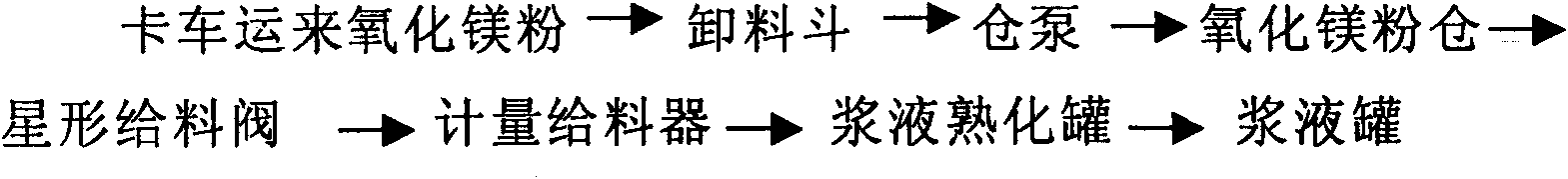
[0189] The system flow is as follows image 3 Shown:
[0190] The magnesia powder in the unloading hopper is pneumatically conveyed to the magnesia powdersilo by the warehouse pump, and the magnesia powder is metered and then input into the aging tank, and mixed with the pulping water from the process water system and the steam in the factory area according to a certain ratio for aging ( Mix 1 part of magnesium oxide desulfurizer with 2.3 parts by weight of water and 0.1 part of water vapor at 20°C, and ripen at 50-60°C for 3 hours), the matured slurry is transported to the slurry tank through the s...
Embodiment 3
[0216] The process of embodiment 3 is similar to embodiment 1, the difference is that,
[0217] In the pulping system, 1 part of magnesium oxide desulfurizer is mixed with 5 parts by weight of water and 0.1 part by weight of steam at °C to generate magnesium hydroxide slurry, which is aged at 80 °C for 2 hours to obtain the slurry of desulfurizer.
[0218] SO 2 In the absorption system, the tower body of the spray absorption tower is a cylindrical body with a constant diameter at the upper and lower parts, and a slurry circulation pump is installed at the lower part of the cylindrical body.
[0219] The obtained technical indicators are as follows:
[0220] Desulfurization efficiency is greater than 95%
[0221] For a 220t / h boiler, the hourly power consumption of this technology is less than 400kW
[0222] The resistance drop of the absorption tower is 600-800Pa.
[0223] Example 3
[0224] The flow process of embodiment 3 is similar to embodiment 1, and difference is, (...
Embodiment 4
[0227] The process of embodiment 4 is similar to that of embodiment 1, the difference is that (1) in the pulping system of process one, a dust removal system is set at the top of the discharge hopper and the powder bin:
[0228] The process of the dust removal system is as follows: Figure 6 shown.
PUM
Abstract
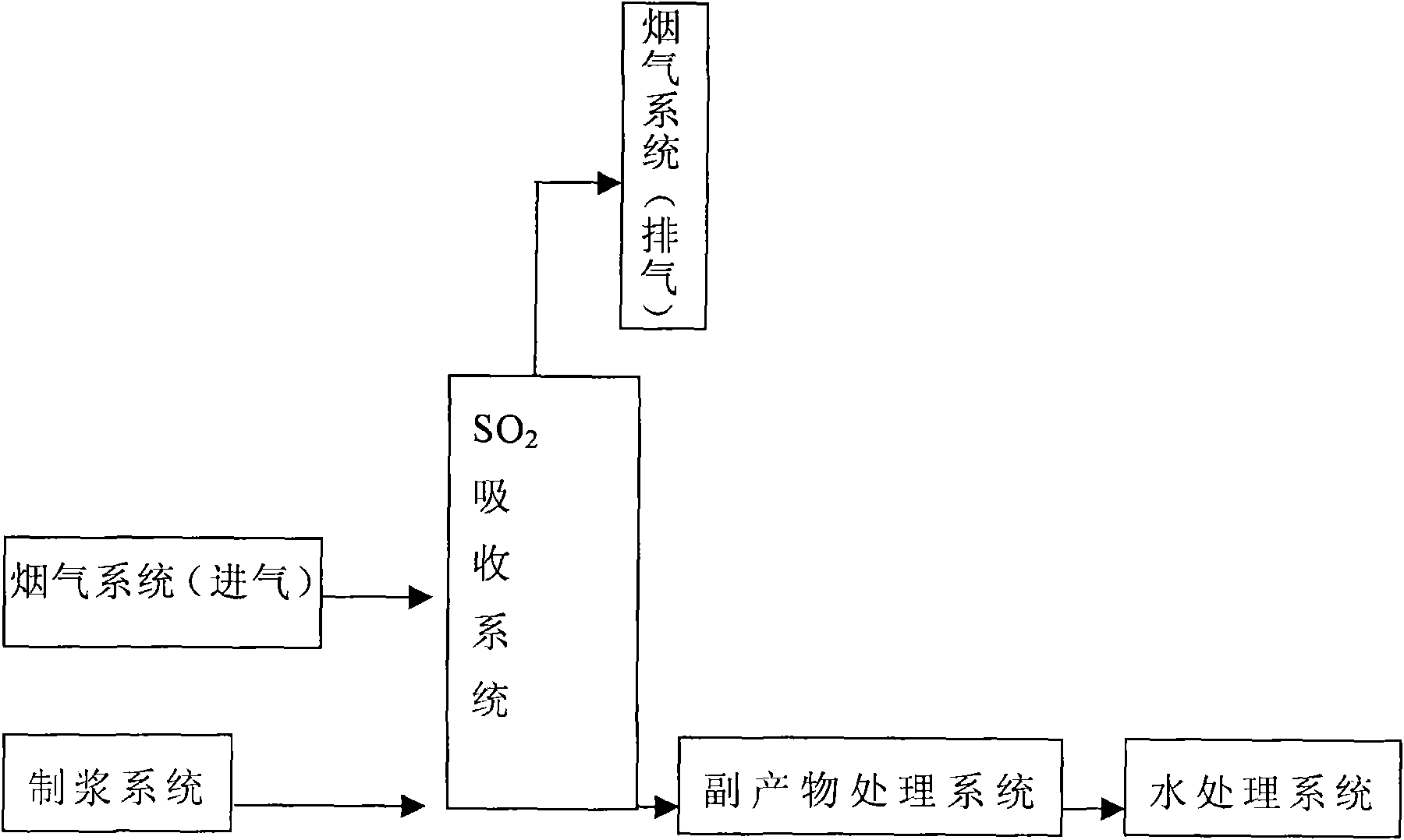
The invention provides an improved magnesium method flue gas desulphurization technique, which comprises the following steps: (a) mixing 1 portion of magnesiumoxide desulfurizing agent with 2.3 to 5 portion of water and 0.1+ / -0.05 portion of water vapor in portion by weight at a temperature of between 0 and 20 DEG C so as to generate a magnesiumhydroxideslurry; (b) ageing the magnesium hydroxideslurry obtained in the step (a) at a temperature of between 50 and 80 DEG C for 2 to 4 hours to obtain a desulfurizing agent slurry; and (c) spraying the desulfurizing agent slurry obtained in the step (b) to perform contact reaction with a flue gas containing sulfur dioxide so as to obtain a magnesium sulfite slurry or a magnesium sulfate slurry and the flue gas without the sulfur dioxide. The process has good reactivity and high desulphurization efficiency, and effectively avoids the problems of scaling, blockage and the like in a desulphurization system.
Description
technical field [0001] The invention relates to a flue gas desulfurization technology, in particular to an improved magnesium method flue gas desulfurization technology. Background technique [0002] Acid deposition and SO 2 Pollution has always been a major environmental issue of concern to the international scientific community and governments. Since the early 1970s, Japan and the United States took the lead in implementing the control of SO 2 Since the emission strategy, many countries have successively formulated strict SO2 emission standards and medium and long-term control strategies, which have accelerated the control of SO2. 2 pace of. [0003] At present, hundreds of flue gas desulfurization technologies have come out, and thousands of flue gas desulfurization devices have been put into operation. Flue gas desulfurization technology can be divided into three types: wet desulfurization technology, semi-dry desulfurization technology and dry desulfurization techno...
Claims
Application Information
Patent Timeline
Application Date:The date an application was filed.
Publication Date:The date a patent or application was officially published.
First Publication Date:The earliest publication date of a patent with the same application number.
Issue Date:Publication date of the patent grant document.
PCT Entry Date:The Entry date of PCT National Phase.
Estimated Expiry Date:The statutory expiry date of a patent right according to the Patent Law, and it is the longest term of protection that the patent right can achieve without the termination of the patent right due to other reasons(Term extension factor has been taken into account ).
Invalid Date:Actual expiry date is based on effective date or publication date of legal transaction data of invalid patent.

