Flameless combustion heat accumulating type flat flame combustion nozzle

A flameless combustion, flat flame burner technology, applied in the direction of burner, combustion ignition, combustion method, etc., can solve the problems of lower performance index, easy direct injection, surrounding parts, easy to brittle cracks, etc., to achieve The effect of reducing NOX emissions, high energy utilization efficiency, and ensuring furnace temperature uniformity

Active Publication Date: 2010-02-03
CHONGQING AOKEQI TECH
View PDF1 Cites 18 Cited by
  • Summary
  • Abstract
  • Description
  • Claims
  • Application Information

AI Technical Summary

Problems solved by technology

[0003] In addition, in the regenerative burner of the prior art, since the flame temperature can reach above 2000°C, it is easy to burn out the pipes and other components around the open flame, resulting in shortened service life; especially the metal pipes, after a period of use burnt out and unusable
However, if a high-temperature-resistant ceramic pipe is used, although the high-temperature resistance performance is improved, the ceramic pipe is prone to embrittlement and damage under the repeated alternating action of cold and heat in the regenerative combustion process, and its service life is still not long
[0004] Finally, due to the different sizes and stacking methods of the parts to be heated in the furnace of the industrial processing furnace, so

Method used


Image

  • Flameless combustion heat accumulating type flat flame combustion nozzle
  • Flameless combustion heat accumulating type flat flame combustion nozzle
  • Flameless combustion heat accumulating type flat flame combustion nozzle

Examples


Example Embodiment

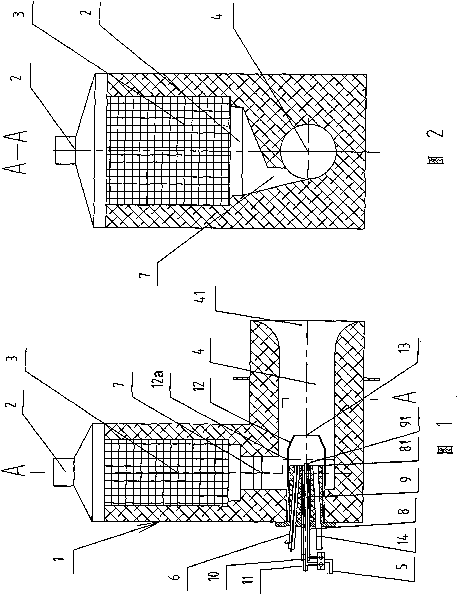
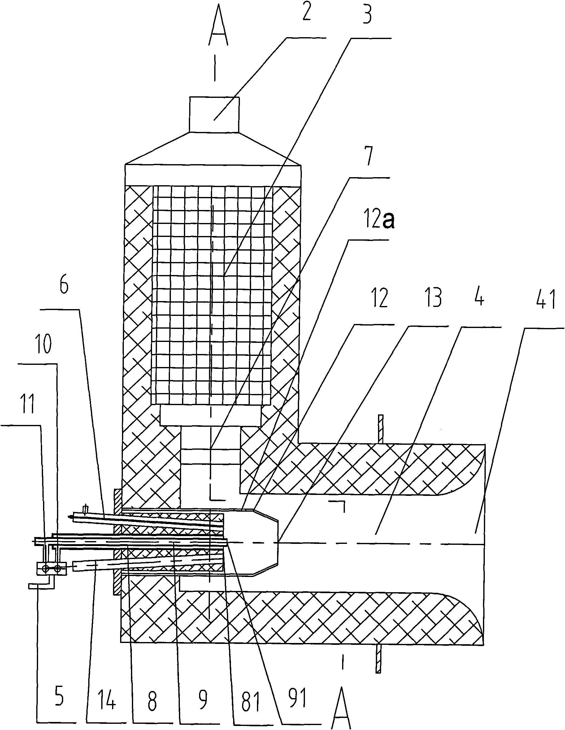
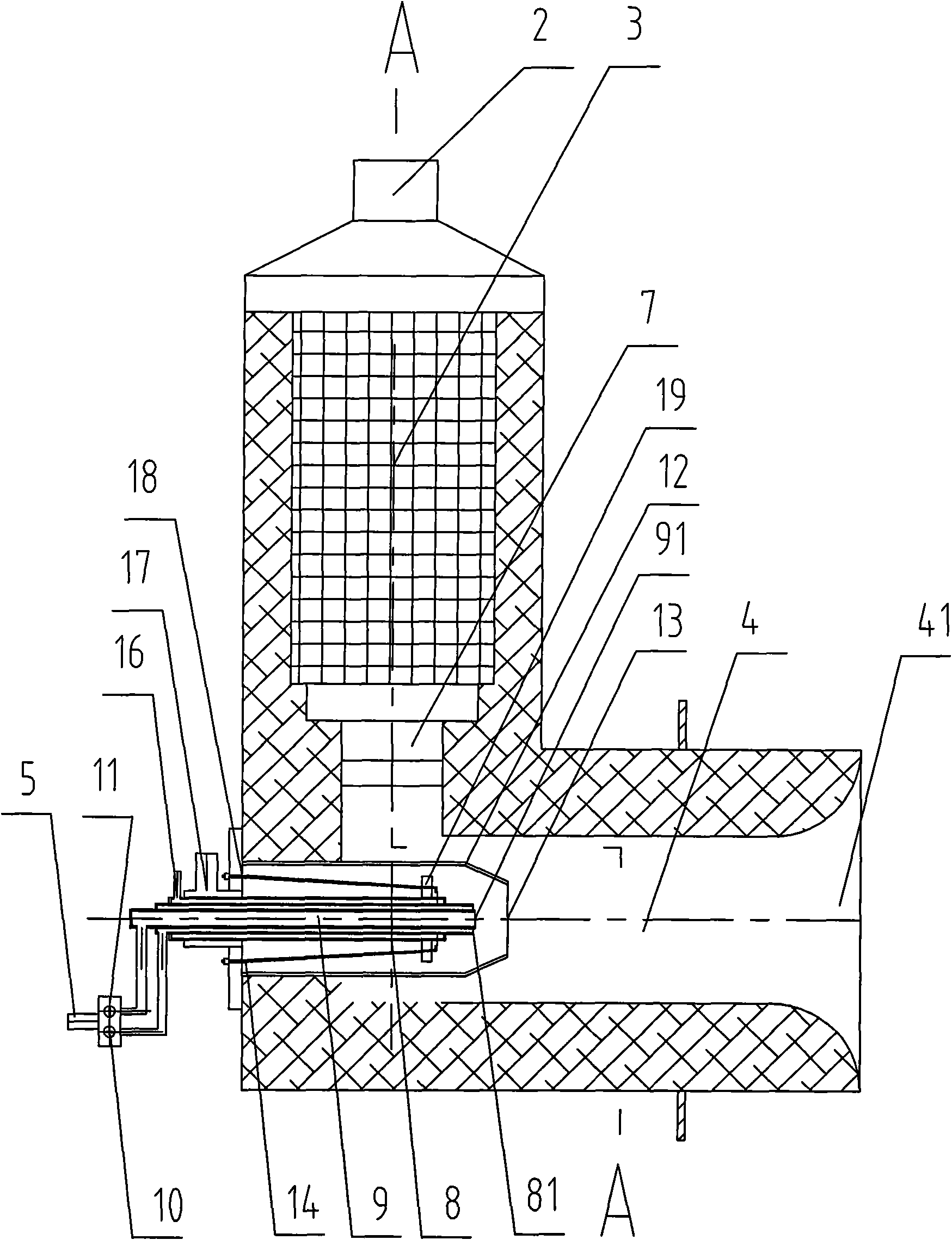
[0024] Such as figure 1 , 2 Among them, the flameless combustion regenerative flat flame burner of the present invention includes a burner body 1, in which an air or flue gas channel 2, a porous heat storage body 3, a combustion cavity 4, and a gas The duct 5 and the ignition device 6, etc., the air or flue gas channel 2 is used as the channel for the combustion-supporting air to enter during combustion, or the flue gas channel for exhausting the flue gas, and the air is input into the burner body 1 (in the combustion cavity 4 and Combustion of gas) or exhaust the flue gas produced by the combustion out of the burner body 1. A porous heat storage body 3 made of refractory materials (such as high-temperature ceramic materials) is arranged in the air or flue gas channel 2 with many The small holes for gas to pass through can exchange heat with the gas when the gas passes; if high-temperature flue gas passes through, the porous heat storage body 3 absorbs the heat of the high-tempe...


PUM


Abstract

The invention discloses a flameless combustion heat accumulating type flat flame combustion nozzle. A combustion nozzle body is internally provided with an air or smoke gas passage, a porous heat accumulator, a combustion cavity, a gas pipeline and an ignition device, wherein the tail end of the air or smoke gas passage is provided with a tangential air inlet duct positioned along the tangential direction of the circumferential combustion cavity, and the air or smoke gas passage is connected with the combustion cavity through the tangential air inlet duct; the tail end of the gas pipeline is provided with a flame combustion gas pipe and a flameless combustion gas pipe which are parallel and respectively controlled by a flame combustion control valve and a flameless combustion control valve, and the aperture of a flameless combustion gas spray orifice positioned on the tail end of the flameless combustion gas pipe is smaller than that of a flame combustion gas spray orifice positioned on the tail end of the flame combustion gas pipe. The flameless combustion heat accumulating type flat flame combustion nozzle has high energy utilization efficiency and good furnace temperature uniformity and can greatly reduce the discharge amount of NOX; fuel is sprayed at high speed through the necking spray orifice, thereby effectively controlling the flame temperature and being beneficial tothe sufficient combustion of the fuel; and in addition, the flame sprays into a furnace cavity with a very short spraying distance so as not to spray to parts inside the furnace cavity.

Description

Technical field [0001] The invention relates to a high, medium and low temperature fuel industrial furnace burner, in particular to a flameless combustion regenerative flat flame burner for high, medium and low temperature fuel industrial furnaces. Background technique [0002] Regenerative combustion technology is currently the best energy-saving combustion technology in the world. Its principle is to use paired burners with regenerators for controlled combustion. When one burner burns, the other burns Inhale and exhaust smoke, the high temperature flue gas exchanges heat energy with the heat storage body when passing through the heat storage body, the heat storage body absorbs heat, and the temperature of the high temperature flue gas is reduced; after a certain period of time, the heat storage body is saturated with heat, and then reverses. When a burner burns, cold air or fuel enters the burner from the heat storage body that has absorbed heat at a higher temperature, and is ...

Claims


Application Information

Patent Timeline
IPC IPC(8): F23D14/22F23D14/46F23D14/58F23D14/66F23D14/76F23Q3/00
CPCY02E20/34
Inventor 顾向涛
Owner CHONGQING AOKEQI TECH
Why Eureka
Try Eureka