
Crack-free electronic beam welding method for titanium metal material and stainless steel

A technology of electron beam welding and titanium metal, which is applied in the direction of electron beam welding equipment, welding equipment, metal processing equipment, etc., can solve the problems of easy cracks, low strength, and poor toughness of titanium metal materials and stainless steel, and achieve improved toughness, Improve the strength and toughness, reduce the effect of thermal stress

Inactive Publication Date: 2011-05-11
HARBIN INST OF TECH
View PDF3 Cites 2 Cited by
  • Summary
  • Abstract
  • Description
  • Claims
  • Application Information

AI Technical Summary

Problems solved by technology

[0003] The purpose of the present invention is to provide a crack-free electron beam welding method for titanium metal materials and stainless steel in order to solve the problems of cracks, low strength and poor toughness in the welding process of titanium metal materials and stainless steel

Method used


Image

  • Crack-free electronic beam welding method for titanium metal material and stainless steel
  • Crack-free electronic beam welding method for titanium metal material and stainless steel
  • Crack-free electronic beam welding method for titanium metal material and stainless steel

Examples


specific Embodiment approach 1

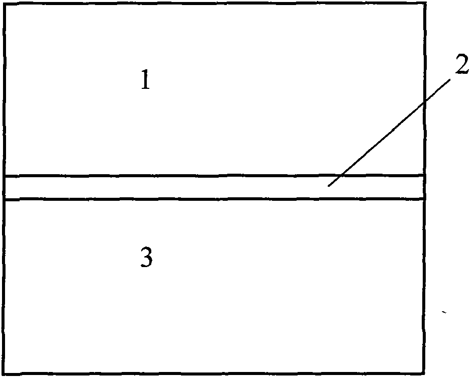
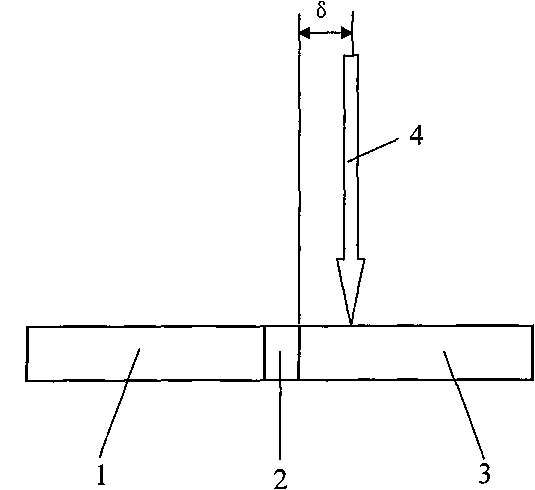
[0012] Specific implementation mode one: (see figure 1 , figure 2 ) The welding method of the present embodiment is realized according to the following steps: One, placing the copper plate 2 with a thickness of 0.5 mm to 2.0 mm and a purity >= 99.95% (quality) as an intermediate layer between the titanium metal material plate 1 to be welded and the stainless steel plate 3 2. Fix the parts to be welded rigidly on the fixture, and use tungsten inert gas welding to fix them by spot welding at both ends, so that the middle layer copper plate 2 is respectively connected to the butt joint surfaces of the titanium metal material plate 1 and the stainless steel plate 3 The gap is 0.05mm ~ 0.25mm; 3. Put the fixed parts to be welded in acetone for 5min ~ 30min ultrasonic cleaning, then pickle, and then dry; The parts are fixed in the electron beam welding vacuum chamber for electron beam welding, and the vacuum degree of the vacuum chamber is 10 -5 Pa~10 -4 Pa, when welding, the el...

specific Embodiment approach 2

[0013] Specific implementation mode two: (see figure 1 , figure 2 ) The difference between this embodiment and the specific embodiment 1 is: the thickness of the copper plate 2 in step 1 is 0.7mm-1.5mm. Others are the same as in the first embodiment.

specific Embodiment approach 3

[0014] Specific implementation mode three: (see figure 1 , figure 2 ) The difference between this embodiment and the first embodiment is: the thickness of the copper plate 2 in the first step is 1.0 mm. Others are the same as in the first embodiment.


PUM

PropertyMeasurementUnit
thicknessaaaaaaaaaa
thicknessaaaaaaaaaa
tensile strengthaaaaaaaaaa

Abstract

The invention relates to a crack-free electronic beam welding method for a titanium metal material and stainless steel, which belongs to the welding field of heterogeneous refractory metal materials. The invention solves the problems of easy crack generation, low strength and poor toughness of a welding component of the prior titanium metal material and stainless steel. The method comprises the following steps: adopting a copper plate as a middle-layer between a titanium metal material plate and a stainless steel plate to form a component to be welded; when the component is welded by an electronic beam, the electronic beam stream faces to a welding seam between the copper plate and the stainless steel plate or is deflected to the side of stainless steel at the welding speed of 200mm / min-600mm / min, the accelerating voltage of 30KV-60KV, the focusing current of 2,000mA-3,000mA and the electronic beam stream of 5mA-15mA; and after the welding is finished, post heating by a defocusing electronic beam. The method can obtain a crack-free welding joint of the titanium metal material and the stainless steel and has the tensile strength of larger than or equal to 230MPa and the yield strength of larger than or equal to 150MPa.

Description

technical field [0001] The invention belongs to the field of dissimilar refractory metal welding, and in particular relates to an electron beam welding method for titanium metal materials and stainless steel. Background technique [0002] The development of the aerospace industry puts forward higher indicators for the performance of the new generation of engines, requiring a substantial increase in the working pressure and temperature of the thrust chamber of the engine, and at the same time increasing the thrust-to-weight ratio of the engine itself to further enhance its rapid maneuverability. Part of the steel body and copper alloy of the engine thrust chamber are replaced by titanium materials, which can achieve a partial weight reduction of 10%-15%, meeting the high-performance requirements of the new generation of liquid oxygen kerosene high-thrust rocket engines and high-altitude differentially guided engines At the same time, the gradual use of titanium metal material...

Claims


Application Information

Patent Timeline
Patent Type & Authority Patents(China)
IPC IPC(8): B23K15/06C23G1/02C21D1/09C21D9/50B23K103/24
Inventor 张秉刚王廷陈国庆冯吉才
Owner HARBIN INST OF TECH
Learn More