
Method for reprocessing spent nuclear fuel and centrifugal extractor therefor

一种提取装置、核燃料的技术,应用在核燃料的再加工领域,能够解决溶剂放射线劣化变大、提取用溶剂寿命变短等问题,达到抑制效果良好的效果

Inactive Publication Date: 2010-02-17
KK TOSHIBA
View PDF4 Cites 8 Cited by
  • Summary
  • Abstract
  • Description
  • Claims
  • Application Information

AI Technical Summary

Problems solved by technology

In addition, even if the final form of reprocessed Pu is U-Pu mixed oxide, and the highly radioactive FP has been removed, there is also the possibility of separate separation and recovery of Pu
[0011] (2) In addition, in the device for reprocessing, the pulsating extraction tower extraction device, in order to improve the efficiency of solvent extraction of atomic nuclides contained in the fuel solution, the partition plate (so-called baffle) in the pulsating extraction tower Multi-layering becomes important, and the device tends to be larger than the centrifugal extraction device
In addition, when the processing speed of solvent extraction is slow, the radiation degradation of the extraction solvent becomes large
Therefore, when reprocessing used nuclear fuel with a high level of radioactivity, such as used nuclear fuel taken out of a high-combustibility nuclear reactor or a fast neutron reactor, it is more useful than a centrifugal extraction device for extraction. Tendency for the life of the solvent to be shortened

Method used


Image

  • Method for reprocessing spent nuclear fuel and centrifugal extractor therefor
  • Method for reprocessing spent nuclear fuel and centrifugal extractor therefor
  • Method for reprocessing spent nuclear fuel and centrifugal extractor therefor

Examples


no. 1 Embodiment approach

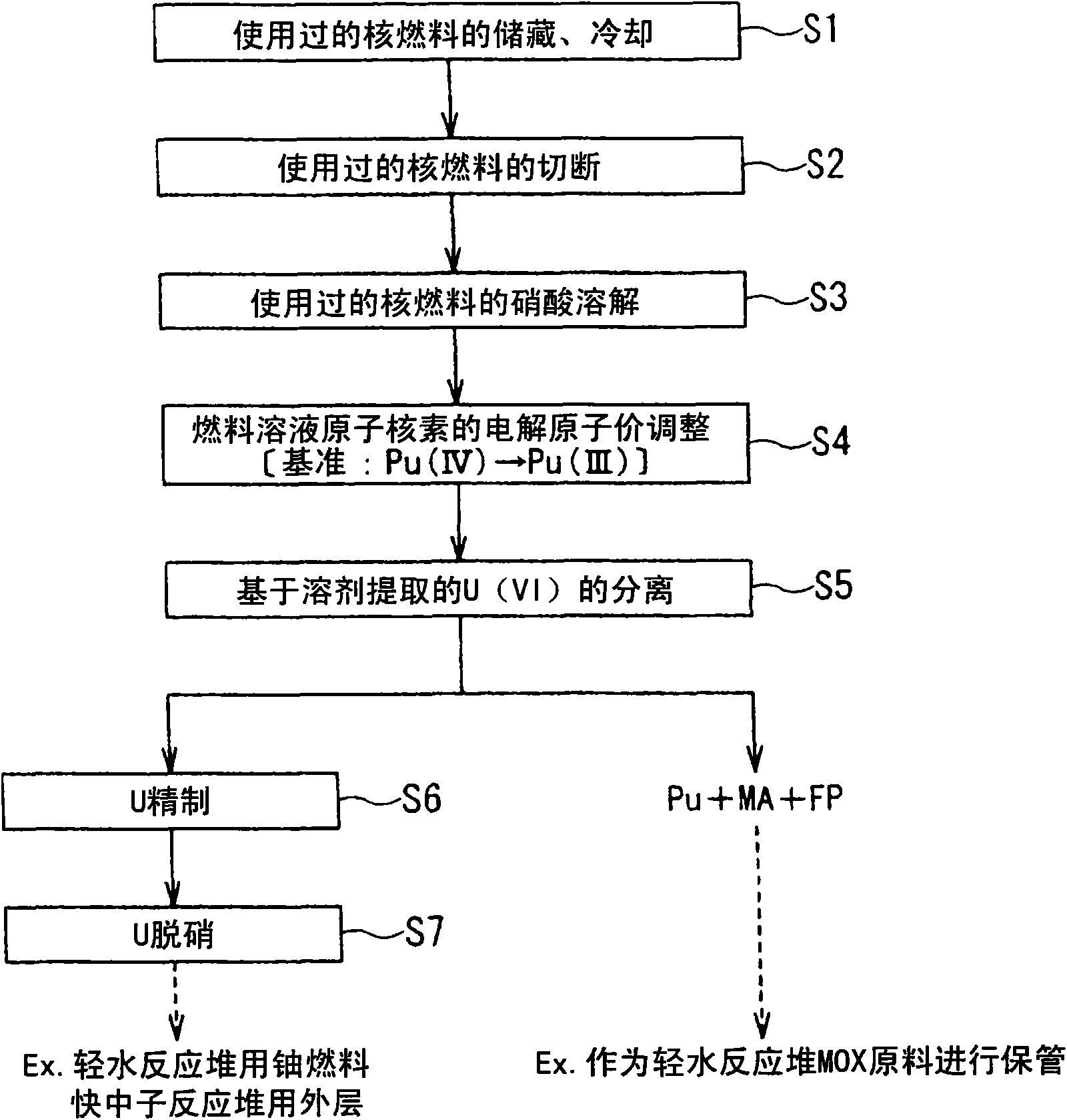
[0055] figure 1 It is a figure which shows the 1st Embodiment of the reprocessing method of the used nuclear fuel of this invention.

[0056]The method for reprocessing used nuclear fuel in this embodiment is based on the pleux method. The pleux method is to dissolve the used nuclear fuel taken out of the nuclear reactor in an aqueous solution of nitric acid, and dissolve the fuel obtained by the dissolution by solvent extraction. The atomic nuclides contained in the liquid are separated and recovered.

[0057] figure 1 It is a flow chart showing the reprocessing process performed by this reprocessing method, and each process of this reprocessing method is demonstrated below.

[0058] Step S1 is a step of storing and cooling the used nuclear fuel taken out of the nuclear reactor in a storage pool until it reaches a predetermined radioactive level (storage and cooling of used nuclear fuel).

[0059] Step S2 is a step of cutting the used nuclear fuel (fuel assembly) cooled an...

no. 2 Embodiment approach

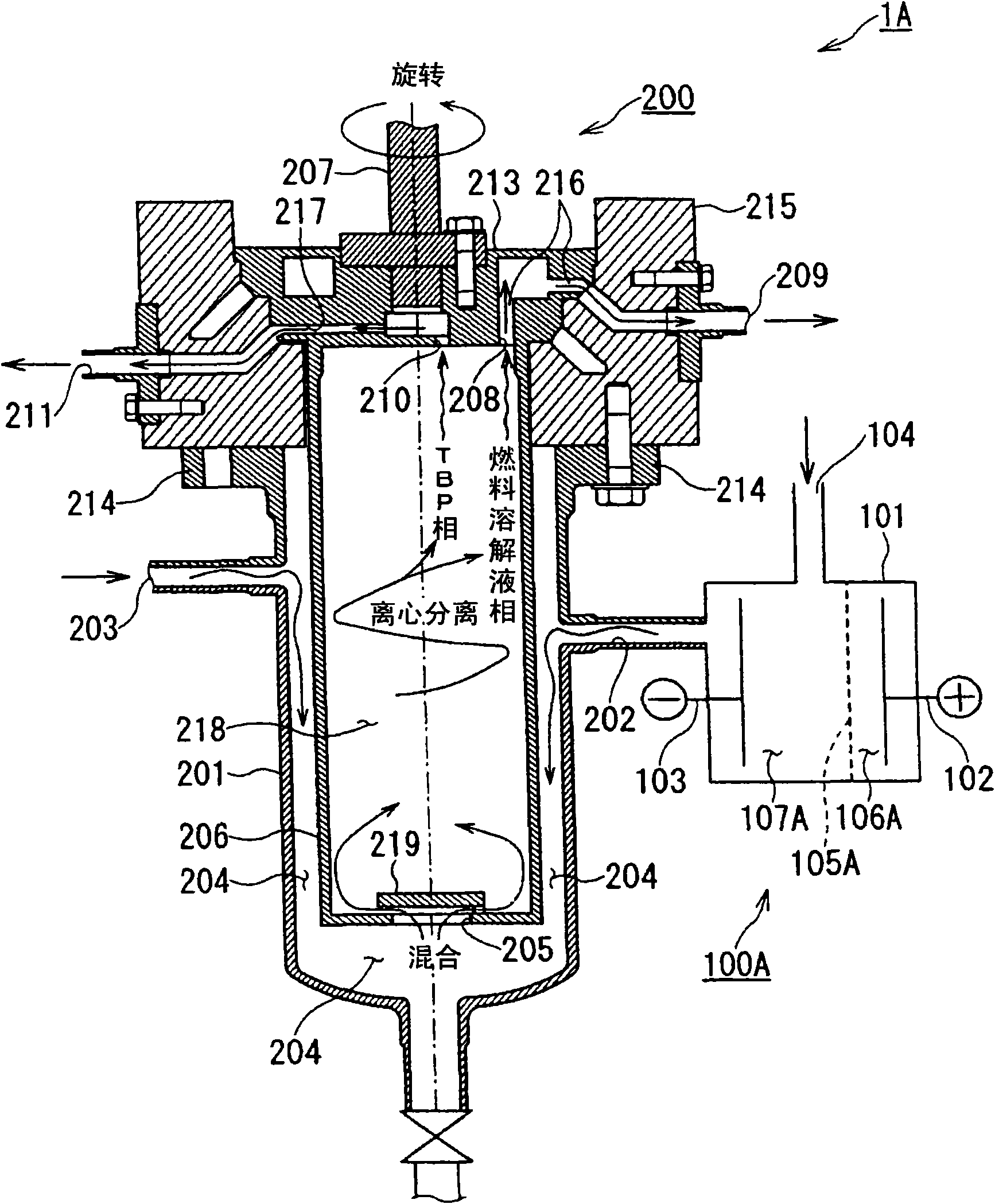
[0101] image 3 It is a figure (longitudinal sectional view) which shows 2nd Embodiment of the centrifugal extraction apparatus of this invention.

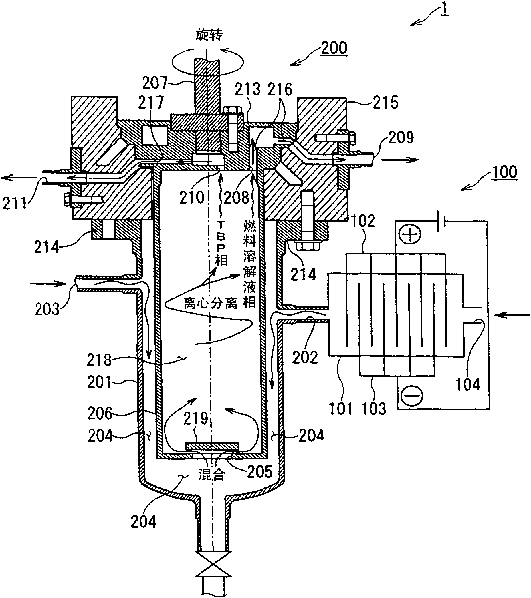
[0102] This embodiment is an example in which the configuration of the electrolytic reduction unit 100 of the centrifugal extraction device 1 of the first embodiment is modified. Note that the same configurations as those of the first embodiment are assigned the same symbols and their descriptions are omitted, and the configurations of the first embodiment that are modified or newly added will be described by adding “A” at the end of the symbols.

[0103] Such as image 3 As shown, the centrifugal extraction device 1A of this embodiment has an electrolytic reduction unit 100A. The electrolytic reduction cell 101 of this electrolytic reduction unit 100A has a diaphragm 105A inside, and an anode chamber 106A and a cathode chamber 107A in which an anode 102 and a cathode 103 are provided via the diaphragm 105A. In addition, in the...

no. 3 Embodiment approach

[0109] Figure 4 It is a figure which shows the 3rd embodiment of the centrifugal extraction apparatus of this invention, Figure 4 (A) is a longitudinal sectional view of the centrifugal extraction device, Figure 4 (B) is Figure 4 (A) III-III sectional view.

[0110] This embodiment is an example in which the configuration of the electrolytic reduction unit 100 of the centrifugal extraction device 1 of the first embodiment is modified. Note that the same configurations as those of the first embodiment are given the same symbols and their descriptions are omitted, and the configurations of the first embodiment that are modified or newly added will be described by adding “B” at the end of the symbols.

[0111] Such as Figure 4 As shown in (A), the centrifugal extraction device 1B of this embodiment has electrolytic reduction units ( 102B, 103B, 202B, 204B). That is, the centrifugal extraction device 1 of the present embodiment is a device in which the centrifugal extrac...


PUM


Abstract

The invention provides a method for reprocessing a spent nuclear fuel which can reprocess highly purified uranium without arranged with a step of separating Pu from solely from a spent nuclear fuel, and solely separated reprocessing of the reprocessed Pu is more difficult and has an excellent repression effect to nuclear proliferation. In a method for reprocessing a spent nuclear fuel by dissolving a spent nuclear fuel in an aqueous nitric acid solution and separating and recovering nuclides contained in the resulting fuel solution by solvent extraction comprising an electrolytic valence adjustment step by using the valence of plutonium contained in the fuel solution as a parameter until the valence of plutonium becomes 3 in which nuclides contained in the fuel solution is electrolyticallyreduced without removing fission products or minor actinides; a nuclide separation step in which, by using an extraction solvent which extracts uranium contained in the fuel solution, uranium is distributed from the fuel solution subjected to the electrolytic valence adjustment step to the extraction solvent.

Description

technical field [0001] The present invention relates to a used nuclear fuel reprocessing technology, in particular to a used nuclear fuel reprocessing method and a centrifugal extraction device used in the reprocessing method. The used nuclear fuel reprocessing method is as follows: Solvent extraction separates and recovers atomic nuclides contained in a fuel solution obtained by dissolving spent nuclear fuel in an aqueous solution of nitric acid. Background technique [0002] In recent years, the use of atomic energy in Japan and many other countries is based on the nuclear fuel cycle including the reprocessing process of used nuclear fuel. The reprocessing of used nuclear fuel is to chemically remove FP (fission product) (fission product) and MA (minoractinide) (minor actinide nuclides; Np, Am, Cm, etc.) The process of separating and recycling U (uranium) and Pu (plutonium) used in atomic reactors plays an important role in the effective use of energy resources and is req...

Claims


Application Information

Patent Timeline
Patent Type & Authority Applications(China)
IPC IPC(8): G21C19/46G21F9/04
CPCB01D17/0217B01D11/0434G21C19/46B01D11/0492B01D17/047B01D17/06Y02W30/50Y02E30/30B01D11/04G21F9/125
Inventor 水口浩司藤田玲子布施行基中村等宇都宫一博田中信彦
Owner KK TOSHIBA
Learn More