
Magnetic field generator insert cartridge for applying magnetic field in molding process of polymer materials

A technology of polymer materials and magnetic field generators, applied in the direction of magnets, magnetic objects, ohmic resistance heating, etc., can solve the problem that the temperature cannot be accurately controlled, and achieve the effect that is conducive to the strength of the magnetic field and the concentration

Inactive Publication Date: 2011-09-07
HARBIN UNIV OF SCI & TECH
View PDF0 Cites 0 Cited by
  • Summary
  • Abstract
  • Description
  • Claims
  • Application Information

AI Technical Summary

Problems solved by technology

[0004] The purpose of the present invention is to solve the problem that the temperature of the heatable pole head of the existing magnetic field generator cannot be accurately controlled during the heating process, so that the thermocompression molding processing and crosslinking (vulcanization) of the polymer material cannot be satisfied while the magnetic field is applied. , curing) reaction to temperature requirements, a magnetic field generator pole head for applying a magnetic field during the molding process of polymer materials is proposed

Method used


Image

  • Magnetic field generator insert cartridge for applying magnetic field in molding process of polymer materials
  • Magnetic field generator insert cartridge for applying magnetic field in molding process of polymer materials
  • Magnetic field generator insert cartridge for applying magnetic field in molding process of polymer materials

Examples


specific Embodiment approach 1

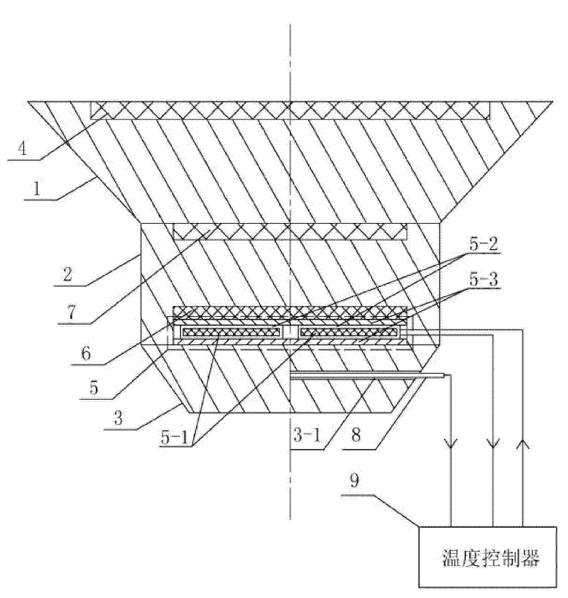
[0011] Specific implementation mode one: the following combination figure 1 Describe this embodiment, this embodiment comprises the first pole head 1, the second pole head 2 and the third pole head 3, and it also includes the first heat insulation layer 4, heating sheet 5, asbestos layer 6, thermocouple 8 and temperature Controller 9, the heating plate 5 is composed of a mica plate 5-1, a resistance wire 5-2 and two insulating plates 5-3, the resistance wire 5-2 is spirally wound on the mica plate 5-1, and the mica plate 5- 1. It is clamped and fixed by two insulating plates 5-3;

[0012] The first pole head 1 and the third pole head 3 are respectively a circular frustum, the second pole head 2 is a cylinder, the large end of the first pole head 1 has a first circular groove, and the first circular groove is provided with the first circular groove. A heat insulation layer 4, the small end face of the first pole head 1 overlaps and is fixedly connected with the upper end face ...

specific Embodiment approach 2

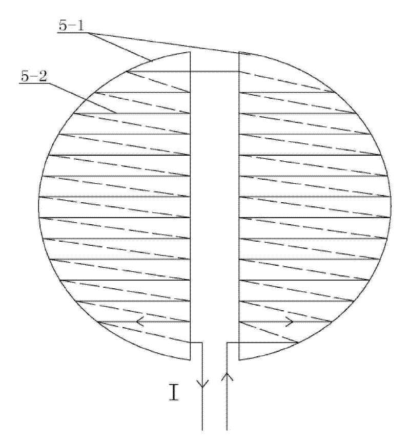
[0016] Specific implementation mode two: the following combination figure 2 Describe this embodiment, the difference between this embodiment and Embodiment 1 is that the mica plate 5-1 is two semicircular mica plates that are arranged axisymmetrically to each other, and the resistance wire 5-2 follows the same turn along the length direction. The distance is spirally wound on each semicircular mica plate in turn. Other components and connections are the same as those in Embodiment 1.

[0017] Since the turn pitch of the resistance wire wound on each semicircular mica board is the same, the heat energy converted from electric energy is evenly distributed. even heating. The heating power of the heating sheet 5 can be adjusted by changing the length of the heating resistance wire 5-2 according to actual needs.

specific Embodiment approach 3

[0018] Embodiment 3: The difference between this embodiment and Embodiment 2 is that the winding direction of the resistance wire 5-2 on the two semicircular mica boards is opposite. Other components and connections are the same as those in Embodiment 2.

[0019] Since the turn pitch of the resistance wire wound on the mica board is the same, and the winding direction is opposite, when the resistance wire is energized, the magnetic field generated by the current is opposite in direction and approximately equal in size, and the two magnetic fields in opposite directions weaken each other, thereby reducing The effect of the additional magnetic field generated by electric heating on the working magnetic field between the heads.


PUM


Abstract

The invention relates to a magnetic field generator insert cartridge for applying a magnetic field in the molding process of polymer materials. The insert cartridge aims to solve the problem that the temperature of the heatable insert cartridge of the prior magnetic field generator can not be accurately controlled in heating process, so the requirements of the hot press molding and the cross linking (vulcanization, curing) reaction of polymer materials on the temperatures can not be met when a magnetic field is applied. The insert cartridge comprises a first insert cartridge, a second insert cartridge, a third insert cartridge, a first heat insulation layer, a heating plate, an asbestos layer, a thermal couple and a temperature controller, wherein the heating plate consists of a mica plate, a resistance wire and two insulating boards; the resistance wire spirally winds around the mica plate; the mica plate is clamped and fixed by the two insulating boards; the thermal couple is inserted in a round hole in the side wall of the third insert cartridge; the cold end of the thermal couple inputs a temperature signal to the temperature controller; and the output of the temperature controller regulates and controls the voltage of the resistance wire. The insert cartridge is used as a magnetic field generator insert cartridge.

Description

technical field [0001] The invention relates to a pole head of a magnetic field generator used for applying a magnetic field during the molding process of polymer materials. Background technique [0002] Magnetic phenomenon is one of the most basic phenomena of matter. Any matter has weak or strong magnetism, and may respond to different degrees of external magnetic field. At present, the use of magnetic fields to assist in the development of new, high-performance polymer materials has become an important research direction in the field of materials science. [0003] With the improvement of experimental methods and the development of quantum chemistry and computer technology, great breakthroughs have been made in the basic theory and experimental research on the influence of external magnetic field on chemical reactions. Configuration and performance, regularity of molecular arrangement, polymerization yield, reaction rate, etc. Recently, some scholars have studied the eff...

Claims


Application Information

Patent Timeline
Patent Type & Authority Patents(China)
IPC IPC(8): H01F7/00H05B3/28
Inventor 韩宝忠韩宝国李长明马凤莲
Owner HARBIN UNIV OF SCI & TECH
Learn More