

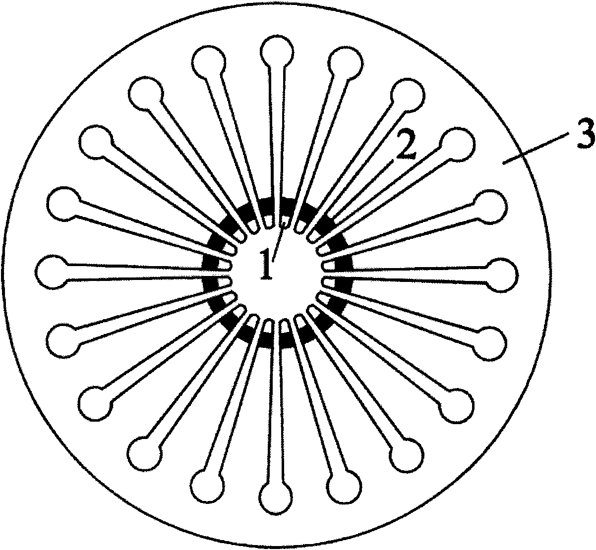
Diaphragm spring and finger tip thermal processing process thereof
A diaphragm spring and process technology, applied in the field of diaphragm spring and its finger end heat treatment process, can solve the problems of visual transition zone, reduction of material yield limit, spring plastic deformation, etc., to reduce costs, reduce labor procedures, and color difference obvious effect
- Summary
- Abstract
- Description
- Claims
- Application Information
AI Technical Summary
Problems solved by technology
Method used
Image

Examples
Embodiment 1
[0014] (1) Heat the clean and dry diaphragm spring to 850°C in a protective atmosphere (such as nitrogen or nitrogen-methanol protective gas), keep it warm for 10 to 20 minutes, and then press and quench it with a cooling water mold (the quenching medium can also be Choose oils, emulsions, etc.).
[0015] (2) Send the quenched diaphragm spring back to the furnace and heat it to 500°C, keep it warm for 30 minutes, and then take it out of the furnace for air cooling.
[0016] (3) Shot peening is carried out on both sides of the diaphragm spring after cooling, and the shot peening time on each side is 40s (the shot material used in this embodiment is cast steel shot, and the diameter is 1.4mm, and the working air pressure is 0.5MPa, and the nozzle is connected to the workpiece. The distance is 30cm).
[0017] (4) Inductively heat the separated fingers of the diaphragm spring at 950° C. for 10 to 15 seconds at a frequency of 250 kHz, and then press-mold and quench with a mold pas...
Embodiment 2
[0020] (1) Heat the clean and dry diaphragm spring to 870°C in a protective atmosphere (such as nitrogen or nitrogen-methanol protective gas), keep it warm for 10 to 20 minutes, and then quench it with a mold passing cooling water (the quenching medium can also be Choose oils, emulsions, etc.).
[0021] (2) Send the quenched diaphragm spring back to the furnace and heat it to 550°C, keep it warm for 20 minutes, and then take it out of the furnace for air cooling.
[0022] (3) Shot peening is carried out on both sides of the diaphragm spring after cooling, and the shot peening time on each side is 40s (the shot material used in this embodiment is cast steel shot, and the diameter is 1.4mm, and the working air pressure is 0.5MPa, and the nozzle is connected to the workpiece. The distance is 30cm).
[0023] (4) Inductively heat the separated fingers of the diaphragm spring at 930° C. for 5 to 10 seconds at a frequency of 300 kHz, and then press-mold and quench with a mold passin...
Embodiment 3
[0026] (1) Heat the clean and dry diaphragm spring to 880°C in a protective atmosphere (such as nitrogen or nitrogen-methanol protective gas), keep it warm for 10 to 20 minutes, and then quench it with a mold with cooling water (the quenching medium can also be Choose oils, emulsions, etc.).
[0027] (2) Return the quenched diaphragm spring to the furnace and heat it to 600°C, keep it warm for 15 minutes, and then take it out of the furnace to cool it in air.
[0028] (3) Shot peening is carried out on both sides of the cooled diaphragm spring, and the shot peening time on each side is 40 to 60s (the shot material used in this embodiment is cast steel shot, the diameter is 1.4mm, the working air pressure is 0.5MPa, the nozzle The distance to the workpiece is 30cm).
[0029] (4) Inductively heat the separated fingers of the diaphragm spring at 920°C at a frequency of 350kHz for 5-10s, and then press-mold and quench with a mold passing through cooling water.
[0030] (5) Put t...
PUM
| Property | Measurement | Unit |
|---|---|---|
| length | aaaaa | aaaaa |
| length | aaaaa | aaaaa |
| length | aaaaa | aaaaa |
Abstract
Description
Claims
Application Information