Solder horn and laser soldering iron using same

A soldering iron head and laser technology, which is applied in the direction of soldering iron, laser welding equipment, manufacturing tools, etc., can solve the problems of shortened service life and easy loss, and achieve the effects of avoiding loss, uniform heat transfer, and fast conduction

Inactive Publication Date: 2010-03-10
李卓
View PDF0 Cites 5 Cited by
  • Summary
  • Abstract
  • Description
  • Claims
  • Application Information

AI Technical Summary

Problems solved by technology

[0004] Another way is to use the soldering iron head as a heat transfer carrier, which can better control the laser, but in the laser welding process, the soldering iron head usually has to withstand higher laser irradiation and accumulate higher heat, which is easier loss and shortened service life

Method used


Image

  • Solder horn and laser soldering iron using same
  • Solder horn and laser soldering iron using same
  • Solder horn and laser soldering iron using same

Examples


Embodiment Construction
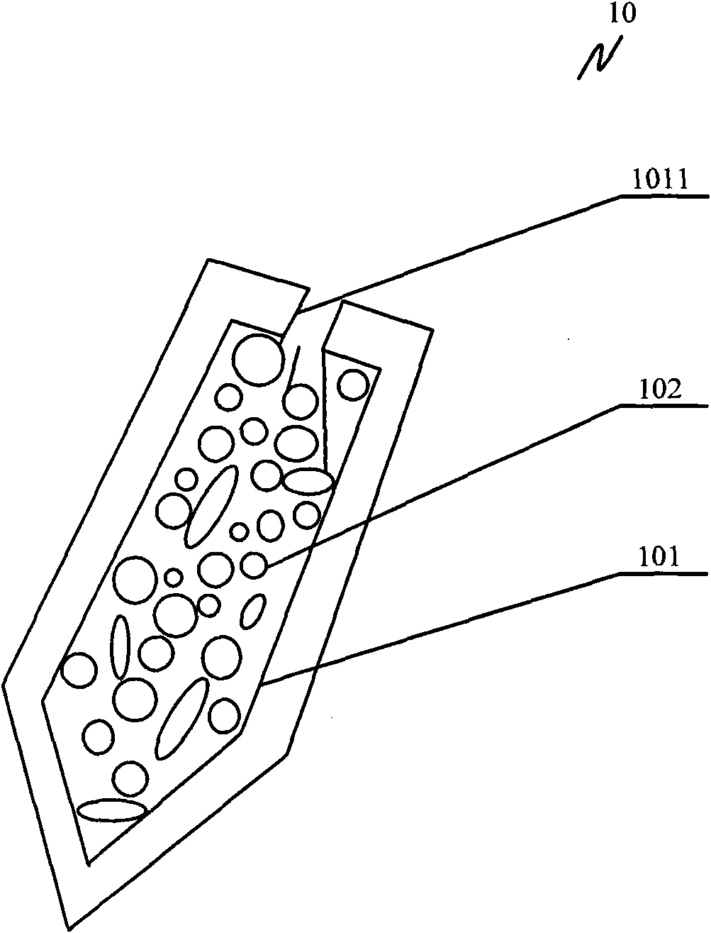
[0037] The main idea of ​​the present invention is to set a hollow cavity in the soldering iron tip, and set a heat-resistant and heat-conducting material in the hollow cavity, so that the heat-resistant and heat-conducting material can be used as a conduction medium to rapidly diverge and conduct the laser light to the inner wall of the soldering iron tip. It has the characteristics of fast conduction and avoids the damage to the soldering iron tip caused by the excessive local heating of the soldering iron tip caused by the excessive concentration of the laser conduction route.

[0038] The technical solutions of the present invention will be described in detail below in conjunction with the accompanying drawings and preferred embodiments.

[0039] refer to figure 1 Shown is a schematic structural view of the first embodiment of the soldering iron tip of the present invention. The soldering iron tip 10 of this embodiment includes a cavity portion 101 , and a heat-resistant ...


PUM


Abstract

The invention discloses a solder horn and a laser soldering iron using same. The laser soldering iron comprises a laser generating device and a solder horn, wherein the solder horn is provided with acavity part, and heat-resisting and heat-conduction materials are arranged in the cavity part; the cavity part is provided with an open end arranged on the non-working part of the solder horn, and laser generated by the laser generating device can be injected in via the open end. The invention uses heat-resisting and heat-conduction materials as the conducting medium so as to quickly diffuse and conduct laser to the inner wall of the cavity part of the solder horn; thus, the invention has the characteristic of quick conduction and avoids harm to the solder horn caused by overquick local warming of the solder horn because laser conduction paths are excessively centralized.

Description

technical field [0001] The invention relates to a soldering iron used for welding, in particular to a soldering iron tip and a laser soldering iron using the soldering iron tip. Background technique [0002] In the manufacturing process of electronic equipment, the welding of electronic components is a very important process. Laser welding is the fastest growing and most promising laser processing technology in recent years. [0003] The welding process is essentially the transfer process of thermal energy from the heat source to the object to be welded. In this process, heat transfer efficiency is a factor that needs to be considered emphatically. Laser welding is especially used in welding dense microelectronic components. The heat energy used to melt the flux is generated by the laser. Usually the laser beam is transmitted through the optical fiber, or the flux directly absorbs the laser light to obtain heat energy and then melts. The energy transfer process does not r...

Claims


Application Information

Patent Timeline
IPC IPC(8): B23K3/02B23K26/42B23K26/70
Inventor 李卓
Owner 李卓
Why Eureka
Try Eureka