Gear rack lifting drilling machine

A gear rack and drilling rig technology, applied in drilling equipment, earth-moving drilling, drilling equipment and methods, etc., can solve the realization and restriction of automatic operations such as precise automatic drilling, automatic discharge and transfer of drill pipes, etc. Process realization, no down pressure load and other problems, to achieve the effect of simple and lightweight base structure, improved safety and work efficiency, and reduced manufacturing and use costs

Inactive Publication Date: 2010-03-10
山东胜利石油石化装备研究中心 +1
View PDF8 Cites 9 Cited by
  • Summary
  • Abstract
  • Description
  • Claims
  • Application Information

AI Technical Summary

Problems solved by technology

Since the lifting system of the existing drilling rig does not have the function of pressing down the load, for some shallow wells and directional wells, the realization of the drilling process is limited
In addition, the lifting system of existing drilling rigs also has c...

Method used


Image

  • Gear rack lifting drilling machine
  • Gear rack lifting drilling machine
  • Gear rack lifting drilling machine

Examples


Embodiment Construction

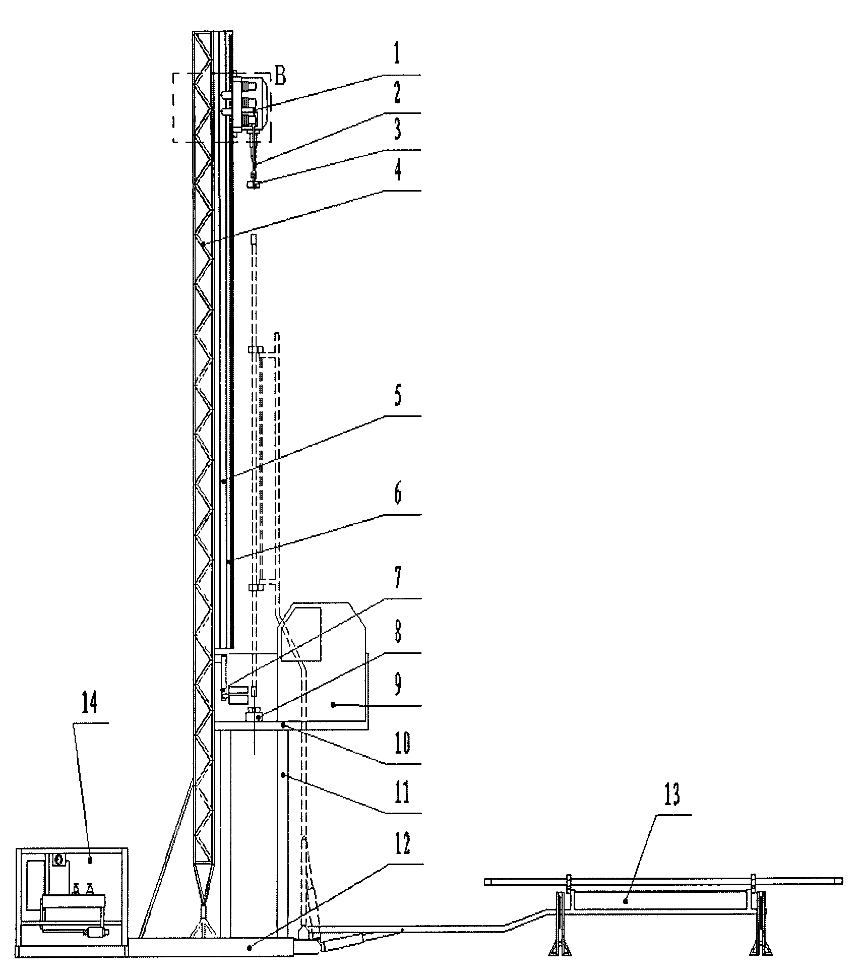
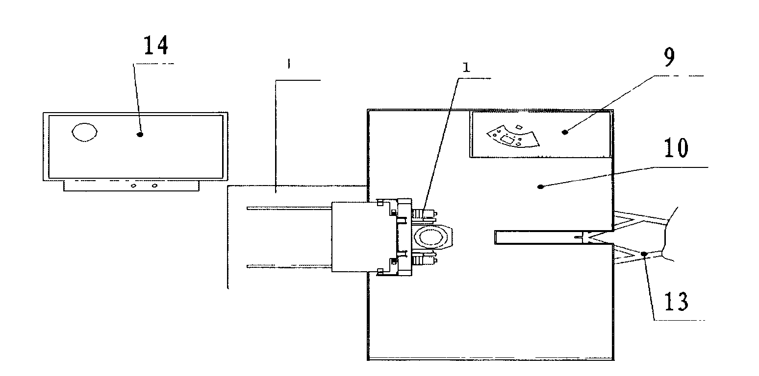
[0025] see figure 1 and figure 2 , the bottom of the derrick 4 is vertically fixed on the base 12, and the two racks 6 and guide rails are respectively symmetrically fixed on both sides of the derrick 4 in parallel. Guide rail 5 reciprocates up and down. Support beam 11 is fixed on the base 12, and operating platform 10 is installed on its upper end. The operation control room 9 is placed on the side of the drilling floor 10 away from the derrick. The hydraulic make-up and breakout mechanism 7 and the hydraulic chuck 8 are placed on the drill floor near the wellhead. One side of the base 12 is provided with a hydraulic drive mechanism 14, and the other side is provided with a drill pipe transfer device 13.

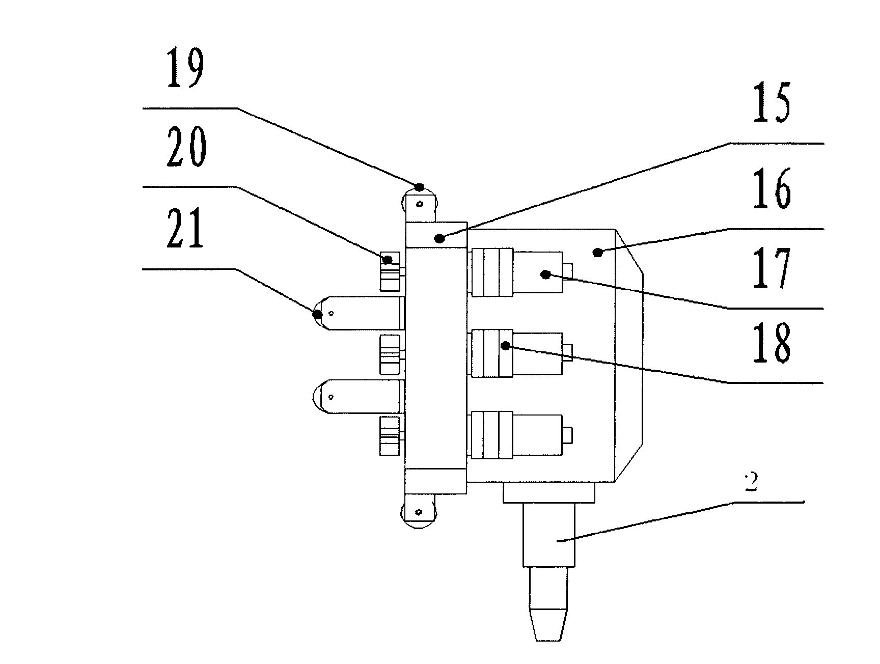
[0026] see image 3 , Figure 6 and Figure 7 , The lifting device 1 includes a main body panel 15, a top drive head 16, a small motor 17, a brake mechanism 18, a front roller 19, a gear 20, a rear roller 21, a suspension ring 2, and an elevator 3. The brake mecha...


PUM


Abstract

The invention relates to the technical field of petroleum drilling machines and equipment, in particular to a gear rack lifting drilling machine. The gear rack lifting drilling machine comprises a headframe body, a base, a tripping device, a drill stem moving device, a chuck, an upper makeup and breakout mechanism, an operating platform and a control device, wherein the headframe body comprises a headframe vertically connected above the base by chains, and two racks and guide rails symmetrically arranged on the same side of the headframe; the tripping device comprises a main body panel, a top driving head arranged on the main body panel, an elevator arranged under the top driving head, a driving motor arranged on the driving panel and roller wheels, wherein after being interlocked with gear wheels, the driving motor is matched with the racks on the headframe, and the roller wheels are matched with the guide rails on the headframe; and the drill stem moving device comprises a lifting arm the inner end of which is hinged with the base, a lifting hydraulic cylinder supporting the lifting arm to rise and fall and a drill stem gripping mechanism arranged on the outer end part of the lifting arm. The invention has the advantages of simplified structure of the drilling machine, convenient installation and transportation, low maintenance cost, long service life, convenient matching with automated devices and wide application.

Description

1. Technical field: [0001] The invention relates to the technical field of oil drilling rig equipment, in particular to a rack and pinion lifting drilling rig. 2. Technical background: [0002] Oil drilling rig is an important equipment for oil exploration and development. With the development of the oil industry, the types and technologies of drilling rigs are also constantly developing. But the mode of hoisting column all is to utilize the hoisting system that is made up of winch, crown block, swimming block, wire rope, hook etc. to hoist. [0003] Existing drilling rigs mainly include a derrick main body, a base, a tripping device, a drill pipe transfer device, a chuck, a make-up and breakout mechanism, a power unit, an operating console and a control device. Among them: the lifting device part (that is, when lifting or lowering the pipe string), the wire rope is wound by the winch, and the wire rope passes through the pulley block composed of the crown block and the sw...

Claims


Application Information

Patent Timeline
IPC IPC(8): E21B7/00E21B15/00
Inventor 杨宪杨玉生王运安杨红伟高仕伟王涛刘磊杜振华
Owner 山东胜利石油石化装备研究中心
Why Eureka
Try Eureka