Plasma etching residue cleaning solution
A technology of etching residue and cleaning solution, applied in the field of cleaning solution, can solve the problems of high metal etching rate, small cleaning operation window, high viscosity and surface tension of cleaning solution, etc. The effect of corrosion rate
Active Publication Date: 2012-08-22
ANJI MICROELECTRONICS TECH (SHANGHAI) CO LTD
View PDF14 Cites 0 Cited by
- Summary
- Abstract
- Description
- Claims
- Application Information
AI Technical Summary
Problems solved by technology
[0005] The technical problem to be solved by the present invention is to overcome the high temperature required for the cleaning of the traditional plasma etching residue cleaning solution. After cleaning, it needs to be rinsed with a solvent. When rinsing with deionized water, the metal etching rate is high and the cleaning operation window is relatively small Small, the viscosity of the cleaning solution and the large surface tension provide a method that can effectively remove the photoresist residue after plasma etching, and can effectively inhibit the corrosion of metals (especially aluminum) and non-metals. Plasma etch residue cleaning solution with large cleaning and rinsing operating window
Method used
View moreImage
Smart ImageViewing Examples

Examples
Embodiment 1~28
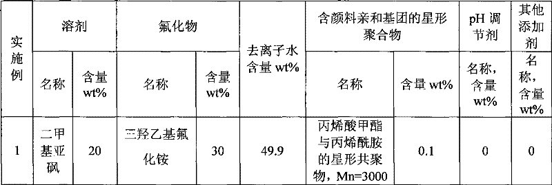
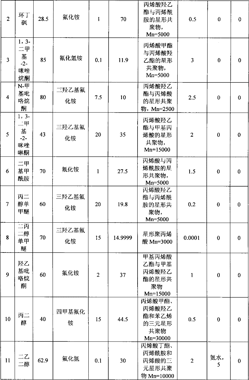
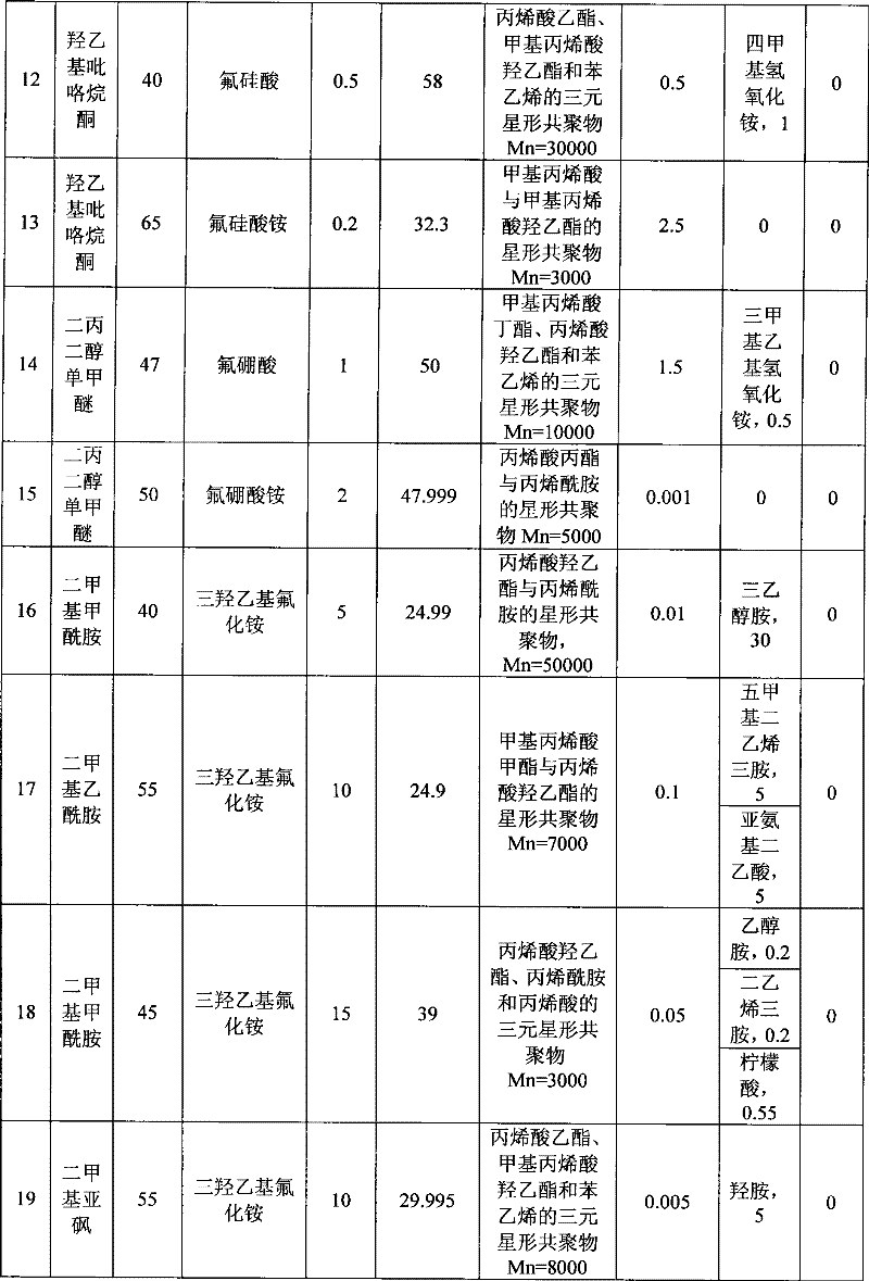
[0027]Table 1 shows Examples 1-28. The plasma etching residue cleaning solution can be obtained by simply mixing the components in each example. Wherein, Mn is the number average molecular weight.
[0028] Table 1 Plasma etching residue cleaning liquid embodiment 1~28
[0029]
[0030]
[0031]
[0032]
[0033]
Login to View More PUM
| Property | Measurement | Unit |
|---|---|---|
| quality score | aaaaa | aaaaa |
Abstract
The invention discloses plasma etching residue cleaning solution, which comprises a solvent, water, fluoride, and a star polymer containing pigment affinity groups. The plasma etching residue cleaning solution can effectively remove photoresist residues after plasma etching, can simultaneously inhibit corrosion of metal (in particular aluminum) and non-metals in high efficiency, and has larger operating windows for cleaning and rinsing.
Description
technical field [0001] The invention relates to a cleaning solution in a semiconductor manufacturing process, in particular to a plasma etching residue cleaning solution. Background technique [0002] In the manufacturing process of semiconductor components, the coating, exposure and imaging of photoresist layers are necessary process steps for the pattern manufacturing of components. Residues of photoresist material need to be completely removed at the end of patterning (ie, after photoresist coating, imaging, ion implantation, and etching) before proceeding to the next process step. Ion bombardment during the doping step hardens the photoresist polymer, thus making the photoresist less soluble and thus more difficult to remove. To date, a two-step process (dry ashing and wet etching) has generally been used in the semiconductor manufacturing industry to remove this photoresist film. The first step is to remove most of the photoresist layer (PR) by dry ashing; the second ...
Claims
Login to View More Application Information
Patent Timeline
 Patent Type & Authority Patents(China)
IPC IPC(8): G03F7/42
CPCG03F7/423C11D7/10C11D11/0047C23G1/00H01L21/02074C11D2111/22
Inventor 刘兵彭洪修彭杏于昊
Owner ANJI MICROELECTRONICS TECH (SHANGHAI) CO LTD
Features
- R&D
- Intellectual Property
- Life Sciences
- Materials
- Tech Scout
- Unparalleled Data Quality
- Higher Quality Content
- 60% Fewer Hallucinations
Learn More Browse by: Latest US Patents, China's latest patents, Technical Efficacy Thesaurus, Application Domain, Technology Topic, Popular Technical Reports.
© 2025 PatSnap. All rights reserved.Legal|Privacy policy|Modern Slavery Act Transparency Statement|Sitemap|About US| Contact US: help@patsnap.com