Method for back washing electrolysis filler in catalytic iron by air and water

A technology that catalyzes iron and internal electrolysis. It is applied in chemical instruments and methods, water/sewage treatment, water/sludge/sewage treatment, etc. It can solve the problems of reducing the treatment effect, reducing the dissolution of iron ions, and affecting the stability of long-term operation. , to achieve the effect of simple method and good reaction effect

Inactive Publication Date: 2010-03-17
ZHENJIANG WATER IND CORP +1
View PDF1 Cites 8 Cited by
  • Summary
  • Abstract
  • Description
  • Claims
  • Application Information

AI Technical Summary

Problems solved by technology

However, in practical applications, since the electrolytic filler in the catalytic iron exists in a static state in the system, although the bulk specific gravity of the filler used is small, the void ratio of the filler can reach more than 95%, and in practical applications, such as sedimentation, air flotation and other pretreatment measures to reduce the concentration of SS in the influent. However, since the electrolytic packing used in the catalytic iron is mainly composed of iron shavings, its surface is very conducive to the attachment of microorganisms. Therefore, with the extension of the running time, a large number of The biofilm attachment layer, especially facing the direction of water flow, this phenomenon is more obvious, which hinders the direct contact between the waste water and the filler and enters the inside of the filler, reduces the dissolution of iron ions, affects the mass transfer efficiency, and reduces the treatment effect. To a certain extent, it affects the long-term operation stability of the technology

Method used


Image

  • Method for back washing electrolysis filler in catalytic iron by air and water

Examples


Embodiment Construction

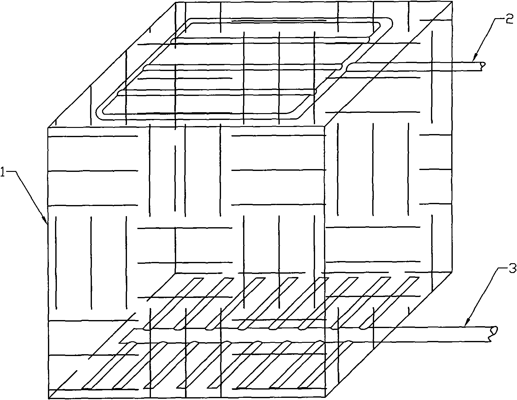
[0013] As shown in the figure, in the device used in the method of the present invention, the catalytic iron inner electrolytic packing 1 installed in the catalytic iron reactor is inserted with a recoil gas pipe 2 connected to a compressed air pipeline and a high-pressure water supply pipeline. Recoil water pipe 3; this system is a downward flow system, so the top surface of the packing is an outer plane facing the direction of water flow, and the recoil water pipe in the shape of a flat grid is 30-50mm away from the top surface of the packing; The shape of the recoil water pipe is arranged at a distance of 30-50mm from the bottom of the filler. If the reactor system is an advection system, the distribution plane of the recoil gas pipe should be set in the vertical direction.

[0014] Example: Pilot-scale catalytic iron and hydrolysis acidification coupling treatment system, the treatment scale is 1.5m 3 / h, the specification of the electrolytic filler in the catalytic iron is 9...


PUM

PropertyMeasurementUnit
pore sizeaaaaaaaaaa
voidageaaaaaaaaaa

Abstract

The invention relates to a maintaining method of a sewage treatment device, in particular to a method for back washing electrolysis filler in catalytic iron by air and water. The method comprises thefollowing steps: inserting back washing air pipes connected with a compressed air pipeline and back washing water pipes connected with a high-pressure water supply pipeline into electrolysis filler incatalytic iron in a catalytic iron reactor; setting distributed planes of the back washing water pipes to be parallel to the bottom plane of the filler and have a distance of 30-50 mm with the bottomplane of the filler, wherein the spraying directions of back washing water outlet holes on the back washing water pipes is downward; setting the distributed planes of the back washing air pipes to beparallel to the outer plane of the filler facing water flows and have a distance of 30-50 mm with the outer plane, wherein the spraying direction of back washing air holes on the back washing air pipes is opposite to the directions of the water flows; and after the catalytic iron reactor is operated for a period of time, back washing the filler by the back washing air pipes and the back washing water pipes. The invention can conveniently and efficiently clear the electrolysis filler in the catalytic iron so as to improve the sewage treatment effect.

Description

Technical field [0001] The invention relates to a maintenance method of a sewage treatment device, in particular to a method for backwashing electrolytic fillers in catalytic iron with air and water. Background technique [0002] Catalytic iron internal electrolysis process sewage treatment device is to add a certain amount of copper as a macro cathode material to the iron internal electrolysis reactor to increase the rate of electrochemical reaction, and reduce the toxic and harmful organic pollution in the wastewater through the method of reduction. It is converted into low-toxic or non-toxic and easily biodegradable substances. At the same time, the iron ions produced during the reaction can precipitate the phosphate in the wastewater, stimulate the metabolism of microorganisms, enhance the filming performance of traditional biological carriers, and promote the proliferation of nitrifying bacteria. Therefore, it can be used as a separate treatment unit or combined with biologi...

Claims


Application Information

Patent Timeline
Patent Type & Authority Applications(China)
IPC IPC(8): C02F1/461
Inventor 胡坚刘志刚赵宝康王红武吴德礼赵冀平马鲁铭喻一萍樊金红张有仓
Owner ZHENJIANG WATER IND CORP
Why Eureka
Try Eureka