
Optimized air-distribution control system for industrial furnace

A technology of industrial furnaces and control systems, applied in the field of control systems, can solve problems such as environmental pollution, lack of fundamental understanding, waste of energy, etc., to ensure combustion quality and furnace pressure, ensure stability, and reduce blast The effect of power consumption

Inactive Publication Date: 2010-03-17
夏学苏
View PDF1 Cites 15 Cited by
  • Summary
  • Abstract
  • Description
  • Claims
  • Application Information

AI Technical Summary

Problems solved by technology

[0002] When industrial furnaces use solid fuel, liquid fuel or gaseous fuel with poor combustion quality, it not only wastes energy greatly, but also seriously pollutes the environment. How to solve this problem has become a topic of much concern and research in the technical field of countries all over the world. , especially in China, due to the extensive development of the economy, the combustion quality of the fuel has not been fundamentally understood. The patent application No. 200710034470.X "Industrial Furnace Combustion Quality Analysis and Control System" has improved the combustion quality of industrial furnace fuel to a certain extent, greatly reduced the emission of nitrogen oxides or carbon monoxide, and saved energy , but this is only to solve the problem from one aspect

Method used


Image

  • Optimized air-distribution control system for industrial furnace

Examples


Embodiment Construction

[0011] The specific implementation manners of the present invention will be further described in detail below in conjunction with the accompanying drawings.

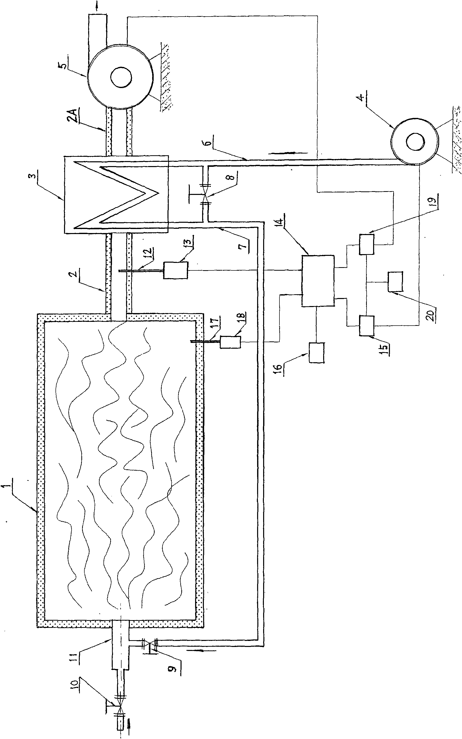
[0012] N (an integer of N≧1) burners 11 are installed on the furnace body 1 . The nozzle of the burner 11 communicates with the inner cavity of the furnace body 1, the feed port of the burner 11 is connected with the fuel delivery pipe through the fuel valve 10, the air inlet end of the burner 11 is connected with one end of the air valve 9, and the other end of the air valve 9 One end is connected to the hot air pipe 7, and the fuel (solid fuel, liquid fuel or gas fuel) enters the burner 11 through the fuel valve 10 and the hot air from the hot air pipe 7 through the air valve 9 is mixed and burned in the burner 11 to improve combustion. The temperature burns and heats the inside of the furnace body 1 . The tail end of the furnace body 1 is connected to the smoke inlet end of the flue 2, the smoke outlet end of the flu...


PUM


Abstract

The invention discloses an optimized air-distribution control system for an industrial furnace. A combustor is connected with a fuel valve and an air valve connected with a hot air tube, a flue is connected with the inlet of a heat exchanger, and the outlet of the heat exchanger is connected with an induced draft fan set driven by an induced draft speed governor. A bypass valve is arranged betweena cold air tube and the hot air tube, and the cold air tube is connected with an air outlet of an air blower set driven by an air blast speed governor. An outlet of a sampling tube is connected withan flue gas oxygen concentration analyzer; a signal output end of the flue gas oxygen concentration analyzer is connected with a first signal input end of a controller, a second signal output end of the controller is connected with a control signal input end of the induced draft speed governor, a furnace pressure duct is connected with a pressure transmitter a signal output end of which is connected with the second signal input end of the controller, the first signal output end of the controller is connected with the control signal input end of the air blast speed governor, and a communicationport of the controller is connected with a human-computer interface. The invention controls the rotate speed of the induced draft fan set and the air blower set driven by the speed governors throughdetecting the pressure and flue gas oxygen concentration values in the furnace on line so that the furnace is in the optimized air-distribution state all the time.

Description

technical field [0001] The invention relates to a control system, in particular to an optimized air distribution system for steel rolling heating furnaces, blast furnace hot blast stoves, glass kilns, cement kilns, lime kilns, ceramic kilns, chemical tube furnaces, steam boilers and other industrial furnaces. Control System. Background technique [0002] When industrial furnaces use solid fuel, liquid fuel or gaseous fuel with poor combustion quality, it not only wastes energy greatly, but also seriously pollutes the environment. How to solve this problem has become a topic of much concern and research in the technical field of countries all over the world. , especially in China, due to the extensive development of the economy, the combustion quality of the fuel has not been fundamentally understood. The patent application No. 200710034470.X "Industrial Furnace Combustion Quality Analysis and Control System" has improved the combustion quality of industrial furnace fuel to ...

Claims


Application Information

Patent Timeline
IPC IPC(8): F23N3/00
Inventor 夏学苏
Owner 夏学苏
Learn More