
Reinforced concrete foundation for mounting assembled tower crane

A reinforced concrete and prefabricated technology, applied in the direction of infrastructure engineering, construction, etc., can solve problems such as costly manual smashing or blasting, affecting engineering construction, and difficult to deal with, so as to ensure safety and physical and mental health, keep clean and hygienic, The effect of high reuse rate

Active Publication Date: 2010-05-19
CHONGQING CONSTR ENG SECOND CONSTR CO LTD +1
View PDF0 Cites 5 Cited by
  • Summary
  • Abstract
  • Description
  • Claims
  • Application Information

AI Technical Summary

Problems solved by technology

Tower crane foundation construction takes at least 15-20 days from earthwork excavation or backfill, steel bar binding, concrete pouring to maintenance. The tower crane cannot be installed and put into production in time, which will have a certain impact on the construction period
[0005](2) High cost
[0006] (3) Failure to meet civilized construction and environmental protection requirements
The cast-in-place reinforced concrete tower foundation will inevitably affect the surrounding environment and generate construction waste, which cannot meet the requirements of civilized construction and environmental protection
[0007] (4) There are many types of cast-in-place fixed tower crane foundations, with different forms, poor versatility, and relatively fixed, generally cannot be reused
[0008] (5) Affects later engineering construction and is not easy to handle
If there are pipelines, septic tanks and other facilities at the base of the tower crane, it will take a lot of manual smashing or blasting to deal with them

Method used


Image

  • Reinforced concrete foundation for mounting assembled tower crane
  • Reinforced concrete foundation for mounting assembled tower crane
  • Reinforced concrete foundation for mounting assembled tower crane

Examples


Embodiment Construction

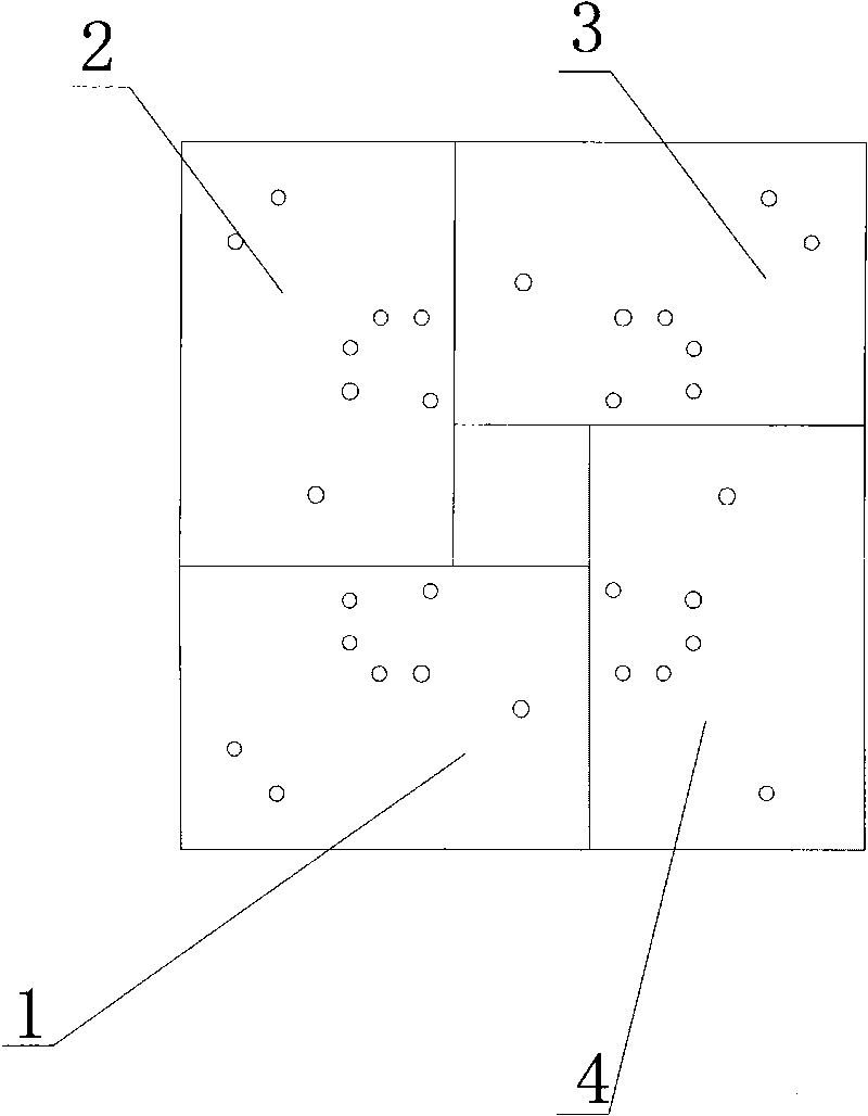
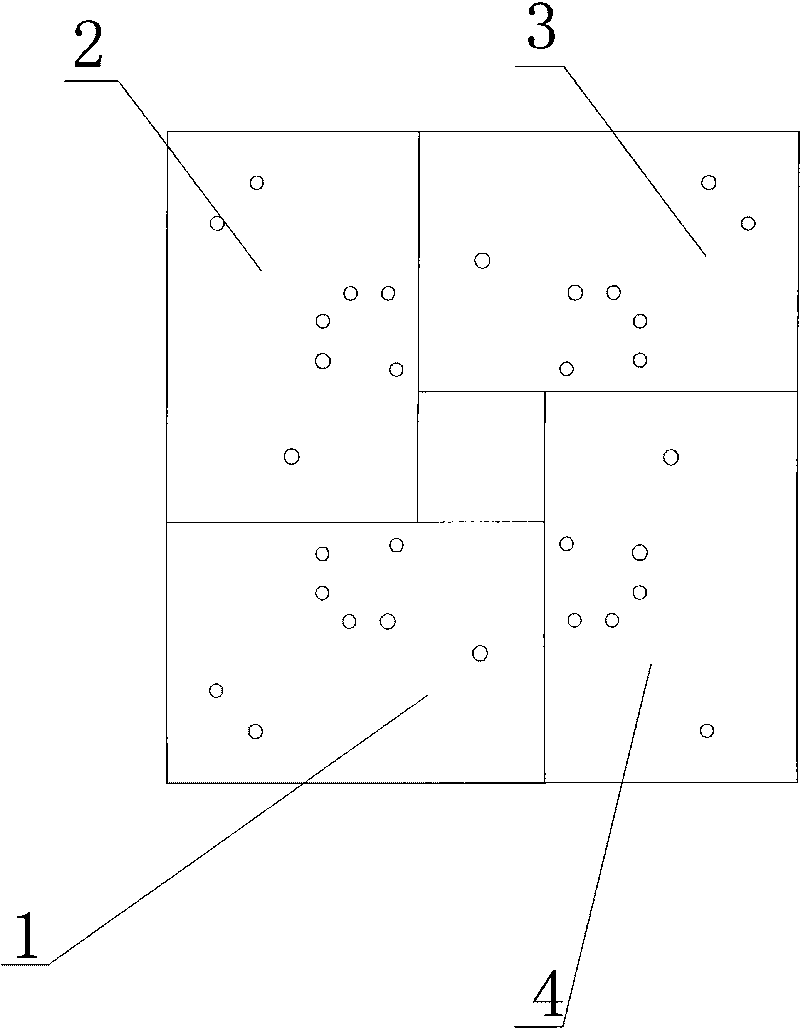
[0022] figure 1 Provided is a schematic plan view of the lower structure of a prefabricated tower crane installed with a reinforced concrete foundation of the present invention, 8 rectangular reinforced concrete blocks with the same shape and size, wherein rectangular reinforced concrete block 1, rectangular reinforced concrete block 2, and rectangular reinforced concrete blocks The concrete block 3 and the rectangular parallelepiped reinforced concrete block 4 form a "back" shape on the same plane.

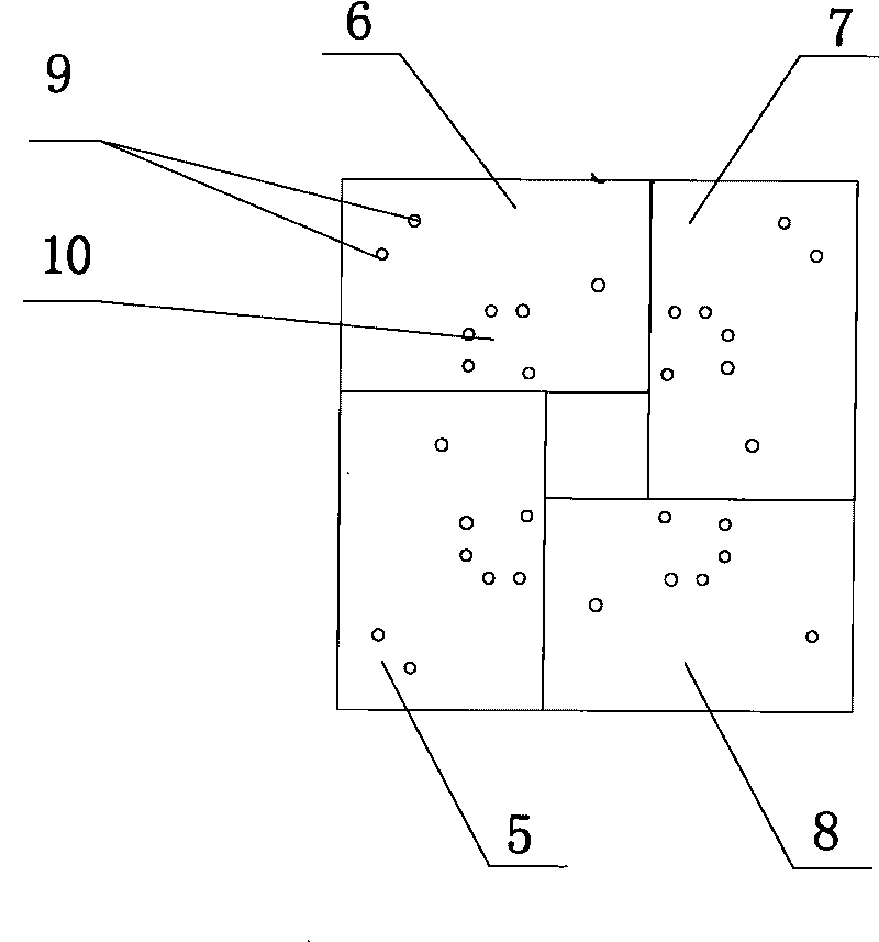
[0023] figure 2 Provided is a schematic plan view of the superstructure of a prefabricated tower crane installed with reinforced concrete foundations of the present invention, cuboid reinforced concrete block 5, cuboid reinforced concrete block 6, cuboid reinforced concrete block 7, and cuboid reinforced concrete block 8 are also surrounded on the same plane. Into the shape of "back". Two "back" shapes are stacked up and down together, wherein, the upper rectangular reinforced...


PUM


Abstract

The invention relates to a reinforced concrete foundation for mounting an assembled tower crane, which is characterized by comprising eight rectangular reinforced concrete blocks of a completely identical shape and in a completely identical size, wherein every four rectangular reinforced concrete blocks are encircled into a rectangular-ambulatory-plane structure in an identical plane; the two rectangular-ambulatory-plane structures are superposed in a way that one is arranged above the other; every two adjacent rectangular reinforced concrete blocks are mutually staggered around the centre of the corresponding rectangular-ambulatory-plane structure for a phase angle of 90 degrees so that each rectangular reinforced concrete block of an upper layer presses the two rectangular reinforced concrete blocks of a lower layer; each rectangular reinforced concrete block is provided with a plurality of pre-embedded connecting holes; the rectangular reinforced concrete blocks of the upper and lower layers run through a part of the pre-embedded connecting holes through a bolt set to be connected into a whole; and the other pre-embedded connecting holes are connected with a tower body structure of a tower crane through the bolt set. The technical scheme has the characteristics of simple structure, good chemical property due to the rectangular-ambulatory-plane structures, quick and convenient mounting and disassembly and remarkable economical and social effect.

Description

technical field [0001] The invention belongs to the field of building construction, and in particular relates to a reinforced concrete foundation used for tower crane installation. Background technique [0002] Stationary tower cranes (tower cranes for short) are the most commonly used vertical transportation tools in construction projects. The design of the tower crane foundation is an important link to ensure the safety and normal use of the tower crane. [0003] At present, the commonly used tower crane foundations are cast-in-place reinforced concrete fixed tower foundations, and the main types are cross-beam type, cross-cross and square combined type, square plate type, square pier type, etc. Through the research on these tower crane foundations, it is found that the traditional tower crane foundations have the following deficiencies: [0004] (1) The construction period is long. It takes a long time to excavate the foundation, make the foundation, maintain the concr...

Claims


Application Information

Patent Timeline
Patent Type & Authority Applications(China)
IPC IPC(8): E02D27/44
Inventor 龚文璞杨有平鲍安红程福强何向东代德智
Owner CHONGQING CONSTR ENG SECOND CONSTR CO LTD
Learn More