
Method for stripping residual pump light in double-coated optical fiber

A double-clad optical fiber, optical fiber technology, applied in clad optical fiber, multi-layer core/clad optical fiber, optics, etc., can solve the problems of coupling device damage and complicated operation, and achieve the effect of convenient implementation and simple structure

Inactive Publication Date: 2010-06-02
SHANGHAI INST OF OPTICS & FINE MECHANICS CHINESE ACAD OF SCI
View PDF0 Cites 58 Cited by
  • Summary
  • Abstract
  • Description
  • Claims
  • Application Information

AI Technical Summary

Problems solved by technology

In all-fiber high-power fiber lasers or amplifiers, the problem of processing the remaining pump light will also be involved, especially in cascade-amplified all-fiber fiber amplifiers, the remaining pump light will be used for the next stage. Coupling devices in the amplification link cause certain damage
Someone proposed to remove the remaining pump light by corroding part of the inner cladding, see ["End-pumped 300W continuous-wave ytterbium dopedall-fiber laser with master oscillator multistage power amplifiers configuration", Optics Express, Vol.16, 2008, 17864~ 17869], but due to the chemical corrosion method, the operation is more cumbersome

Method used


Image

  • Method for stripping residual pump light in double-coated optical fiber
  • Method for stripping residual pump light in double-coated optical fiber
  • Method for stripping residual pump light in double-coated optical fiber

Examples


Embodiment Construction

[0019] The present invention will be further described below in conjunction with the accompanying drawings and embodiments, but the protection scope of the present invention should not be limited thereby.

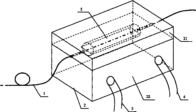
[0020] see figure 1 , figure 1 It is a structural schematic diagram of the method for stripping the remaining pump light in the double-clad optical fiber of the present invention. As can be seen from the figure, the method for stripping the remaining pump light in the double-clad optical fiber of the present invention comprises the following steps:

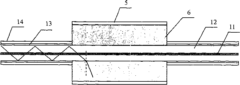
[0021] 1. the double-clad fiber 1 at the output end of the all-fiber laser removes a section of outer cladding 13 and coating 14, and then a section of quartz tube 5 is placed on the inner cladding coat of the section of optical fiber, and the quartz tube 5 and A high refractive index optical gel 6 is filled between the inner cladding of the optical fiber, see figure 2 ;

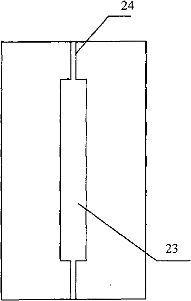
[0022] ②Preparation of the heat sink 2, the heat s...


PUM


Abstract

The invention relates to a method for stripping residual pump light in a double-coated optical fiber, which comprises the steps of: removing an outer coating and a cladding layer of one section of the double-coated optical fiber at the output end of a full optical fiber laser; covering optical gel with high refractive index outside an inner coating of the section of the optical fiber, wherein the refractive index of the optical gel is higher than that of the inner coating of the double-coated optical fiber; leaking light transmitted in the inner coating out through the optical gel, and fully absorbing the leaded pump light with high power by a heat radiating device. The invention has the characteristics of compact structure and convenient integration, and can be applied to a high-power optical fiber laser or high-power optical fiber amplifier.

Description

technical field [0001] The invention relates to a fiber laser and a fiber amplifier, in particular to a method for stripping the remaining pumping light in a double-clad fiber for an all-fiber laser. Background technique [0002] In fiber lasers and fiber amplifiers built from discrete components, dichroic filters are often used to filter out residual pump light. With the expansion of fiber laser applications, all-fiber lasers or amplifiers have become the best way for industrialization and practicality. In all-fiber high-power fiber lasers or amplifiers, the problem of processing the remaining pump light will also be involved, especially in cascade-amplified all-fiber fiber amplifiers, the remaining pump light will be used for the next stage. The coupling devices in the amplification link cause certain damage. Someone proposed to remove the remaining pump light by corroding part of the inner cladding, see ["End-pumped 300W continuous-wave ytterbium dopedall-fiber laser wi...

Claims


Application Information

Patent Timeline
IPC IPC(8): G02F1/01G02B6/036
Inventor 何兵李震周军楼祺洪
Owner SHANGHAI INST OF OPTICS & FINE MECHANICS CHINESE ACAD OF SCI
Learn More