Method and equipment for preparing hydrocarbon by methyl alcohol or/ and dimethyl ether

A technology for producing hydrocarbons and dimethyl ether from dimethyl ether, which is applied in the field of chemical engineering and can solve the problems of high cycle ratio, increased energy consumption, and high energy consumption

Active Publication Date: 2010-06-09
杭州林达化工技术工程有限公司
View PDF2 Cites 15 Cited by
  • Summary
  • Abstract
  • Description
  • Claims
  • Application Information

AI Technical Summary

Problems solved by technology

The former such as the MTG method of Exxon mobil company (edited by Gao Jinsheng, Coal Liquefaction Technology, Chemical Industry Press, March 2005), generates dimethyl ether through methanol dehydration, and dimethyl ether is further dehydrated to generate hydrocarbons. The main product of the MTG method is Gasoline, product quality is good, less methane is produced, but the cycle ratio is as high as 9, the reactor is large, and the energy consumption is

Method used


Image

  • Method and equipment for preparing hydrocarbon by methyl alcohol or/ and dimethyl ether
  • Method and equipment for preparing hydrocarbon by methyl alcohol or/ and dimethyl ether
  • Method and equipment for preparing hydrocarbon by methyl alcohol or/ and dimethyl ether

Examples


Embodiment 1

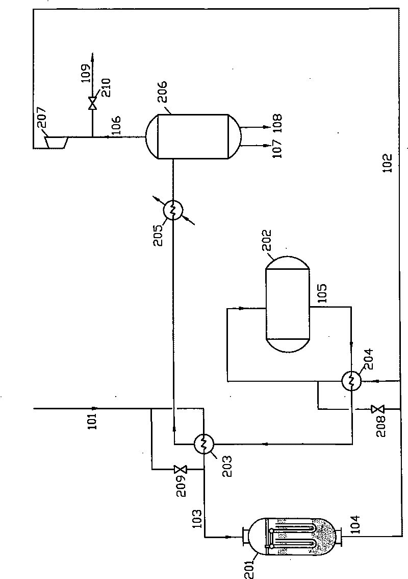
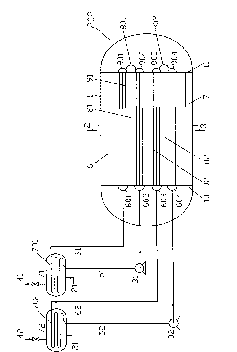
[0030] Embodiment 1: the MTG production process is as follows with methanol gasoline figure 1 , the methanol dehydration reactor 201 adopts a homogeneous dimethyl ether reactor with a diameter of 2.2 meters and a built-in gamma-alumina 30M 3 , the alkylation reactor 202 adopts such as figure 2 Horizontal heat exchange reactor, diameter 3.8 meters, catalyst layer 81, 82 filled with ZSM-5 molecular sieve catalyst 120M 3, the pressure is 2.5MPa, heated to about 130°C, the methanol gas enters the methanol dehydration reactor 201, the heat exchange tube, the absorption tube, and the catalyst layer outside the catalyst layer are heated and then exit the heat exchange tube, and are carried out on the catalyst layer at a temperature of about 300°C Methanol dehydration reaction, the gas out of the tower and the gas out of the alkylation tower exchange heat at 390°C and enter the alkylation reactor 202 for dehydration to generate hydrocarbons. Then in the catalytic reaction zone 81 a...

Embodiment 2

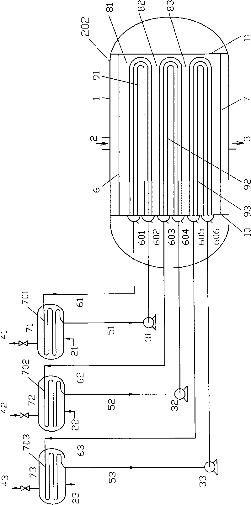
[0033] Embodiment 2: with containing H 2 O 20% crude methanol is used as raw material to make propylene but MTP, the production process is shown in figure 1 . Methanol dehydration reactor 201 is an air-cooled self-heating reactor with a diameter of 2 meters and a built-in γ-alumina catalyst of 20M 3 , the alkylation reactor 202 adopts image 3 The shown horizontal heat exchange reactor, with a diameter of 3.6 meters, contains SAPO-34MTP molecular sieve catalyst 120M 3 , the pressure is 0.2MPa, the methanol heated to 120°C enters the dehydration reactor 201, and dehydrates at a temperature of about 300°C through internal heat exchange. The heat is exchanged to 430°C and enters the hydrocarbonation reactor 202 to react at a temperature of 450-480°C, and the heat of reaction is absorbed by the molten salt (KNO 3 53%, NaNO 2 40%, NaNO 3 7%) absorption, the temperature difference between the hot spot temperature of the catalyst in the reaction zone and the temperature of the ...


PUM


Abstract

The invention discloses a method and equipment for preparing hydrocarbon by methyl alcohol or/ and dimethyl ether. The invention is mainly characterized in that raw material gases, such as methyl alcohol or/ and dimethyl ether and the like pass through fixed bed reaction composition equipment for catalysis to generate hydrocarbon, wherein the fixed bed reaction combination equipment is at least provided with two reaction zones, and each reaction zone is provided with a heat exchange tube set capable of independently adjusting heat exchange medium temperature; after reaction gases separate target product hydrocarbon and water by heat exchange and cooling, expect that less chillout recycle gas is mixed with raw material gas, reaction for generating target product hydrocarbon is carried out.The invention has the beneficial effects of small catalyst layer temperature difference, low recycle ratio, high synthetic ratio, small investment, high output, energy saving and consumption reduction.

Description

technical field [0001] The invention relates to a method and equipment for producing hydrocarbons with methanol or / and dimethyl ether, belonging to the field of chemical engineering. Background technique [0002] Using methanol or / and dimethyl ether to produce hydrocarbons, one type of product is mainly gasoline as energy, and the other type of low-carbon olefins is mainly propylene and ethylene as chemical raw materials. The former such as the MTG method of Exxon mobil company (edited by Gao Jinsheng, Coal Liquefaction Technology, Chemical Industry Press, March 2005), generates dimethyl ether through methanol dehydration, and dimethyl ether is further dehydrated to generate hydrocarbons. The main product of the MTG method is Gasoline has good product quality and produces less methane, but the cycle ratio is as high as 9, the reactor is large, and the energy consumption is high. The latter, such as German Lurgi Company, uses methanol to produce low-carbon olefins such as pr...

Claims


Application Information

Patent Timeline
IPC IPC(8): C07C1/20C07C11/02C10G3/00
CPCY02P20/52Y02P30/20
Inventor 楼韧楼寿林
Owner 杭州林达化工技术工程有限公司
Why Eureka
Try Eureka