Slow wave structure used for X-waveband space travelling wave tube

A technology of slow wave structure and traveling wave tube, applied in the field of slow wave structure, can solve the problems of self-excited oscillation and low electronic efficiency of the traveling wave tube, and achieve the effect of improving the total efficiency

Inactive Publication Date: 2010-06-09
HUADONG PHOTOELECTRIC TECHN INST OF ANHUI PROVINCE
View PDF0 Cites 12 Cited by
  • Summary
  • Abstract
  • Description
  • Claims
  • Application Information

AI Technical Summary

Problems solved by technology

Since the electron beam and the high-frequency signal can interact effectively only under synchronous conditions, the energy that the electron beam can hand over to the high-frequency field is only the kinetic energy corresponding to the part w...

Method used


Image

  • Slow wave structure used for X-waveband space travelling wave tube
  • Slow wave structure used for X-waveband space travelling wave tube
  • Slow wave structure used for X-waveband space travelling wave tube

Examples


Embodiment Construction

[0019] 1) According to the technical index requirements of the tube, select the cathode current I k =60mA, slow wave voltage V 0 =3900V, calculate the physical parameters such as the speed of the electron beam, the power of the high-frequency input signal, the phase velocity, the wavelength of the guided wave, the reduction ratio, the axial phase constant and the radial phase constant;

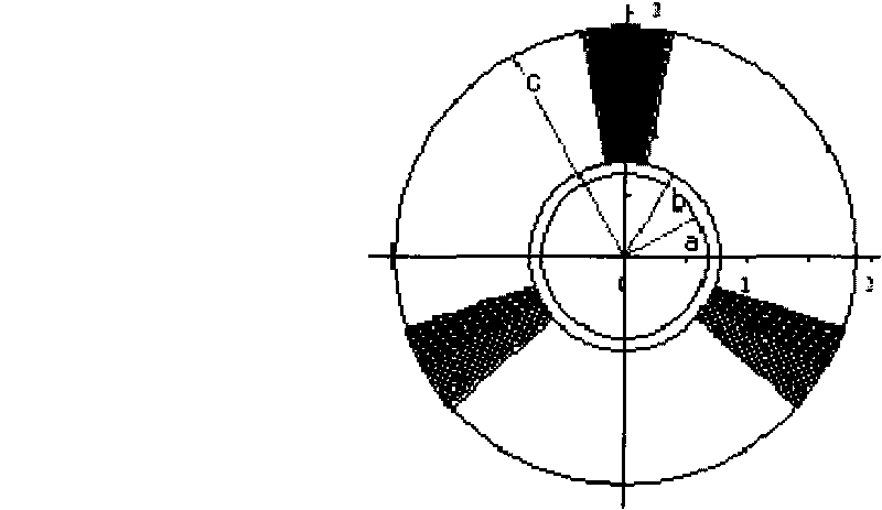
[0020] 2) Calculate the average radius and channel radius of the helix, select a high-purity vacuum-smelted molybdenum helix of 0.13mm×0.26mm, a Monel tube shell with an inner diameter of R=1.9mm, and a wedge-shaped BeO99 clamping rod with good thermal conductivity. The cross-sectional view of the wave assembly structure is shown in figure 1 shown;

[0021] 3) Take λ p / L=3.5, get L=λ p / 3.5=7.03mm, to determine the magnetic field period is 7.0mm, where λ p = 3.592 × 10 - 2 ...


PUM

PropertyMeasurementUnit
Lengthaaaaaaaaaa
Pitchaaaaaaaaaa

Abstract

The invention discloses a slow wave structure used for an X-waveband space travelling wave tube. A tube shell adopts a Monel tube shell with the inner diameter of 1.9 millimeters, a holding rod is made of a wedge-shaped BeO99 material, the slow wave structure adopts a high-pure vacuum smelted molybdenum helix of 0.13mm*0.26mm, the helix at the output section of the slow wave structure has a plurality of sections with different thread pitches, and a two-section carbon film attenuator is selected for inhibiting self-oscillation. The slow wave system has the advantages of large coupling impedance, strong heat dissipation capability, high interactive efficiency and the like, and is suitable for the space travelling wave tube.

Description

technical field [0001] The invention belongs to the field of microwave electric vacuum devices, in particular to a slow wave structure used for X-band space traveling wave tubes. Background technique [0002] The space traveling wave tube is the key component of the communication, navigation, data transmission and other payload systems of aerospace equipment, as well as the spaceborne transponder and the synthetic aperture radar (SAR) transmitter, and requires high efficiency. In the traveling wave tube, the high-frequency signal is transmitted axially along the slow wave line, and is amplified by the kinetic energy of the electron beam during the traveling process. Therefore, the interaction efficiency of the high-frequency signal and the electron beam is a key factor affecting the overall efficiency of the TWT. [0003] The design of high-efficiency slow-wave system is an important link in the development of space traveling wave tubes. Since the electron beam and the hig...

Claims


Application Information

Patent Timeline
IPC IPC(8): H01J23/27
Inventor 吴华夏贺兆昌法朋亭高红梅
Owner HUADONG PHOTOELECTRIC TECHN INST OF ANHUI PROVINCE
Why Eureka
Try Eureka