
Hydraulic control loop used for jackdrill and control system thereof

A control loop, rock drill technology, applied in mechanical equipment, fluid pressure actuating devices, drilling equipment, etc., can solve the problems of harsh working environment, affecting the personal safety of operators, large vibration and impact of rock drills, etc., to overcome inaccurate positioning and drilling , The effect of reducing manufacturing cost and low labor intensity

Inactive Publication Date: 2010-06-23
SANY HEAVY EQUIP
View PDF0 Cites 40 Cited by
  • Summary
  • Abstract
  • Description
  • Claims
  • Application Information

AI Technical Summary

Problems solved by technology

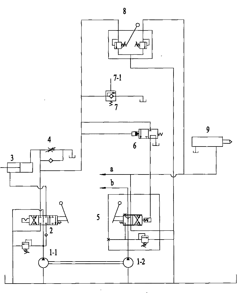
[0011] In the above-mentioned hydraulic control circuit for the rock drill, the adjustment of the oil pressure required for the work of the rock drill is always completed by manually operating the drilling valve 8 step by step. The control performance is poor; due to the manual operation, the stability of the rock drill is not guaranteed, and the positioning and drilling accuracy is low; due to the manual operation of the step-by-step drilling valve 8 and the manual multi-way valve 2, the operator only needs to It can be operated on the machine. The vibration and impact of the rock drill is relatively large when it is working, and the working environment is relatively harsh, which will affect the personal safety of the operator.
[0012] In addition, in the above-mentioned hydraulic control circuit for rock drills, one hydraulic pump cannot realize the compound action of multiple actuators. Only by adding a hydraulic pump can multiple actuators perform compound actions. For example, in order to realize simultaneous actions of propulsion and rock drilling, Two hydraulic pumps are used, adding more hydraulic pumps makes the manufacturing cost of the rock drill higher

Method used


Image

  • Hydraulic control loop used for jackdrill and control system thereof
  • Hydraulic control loop used for jackdrill and control system thereof
  • Hydraulic control loop used for jackdrill and control system thereof

Examples


Embodiment Construction

[0043] The content of the present invention will be described below in conjunction with the accompanying drawings. The following description is only exemplary and explanatory, and should not have any limiting effect on the protection scope of the present invention.

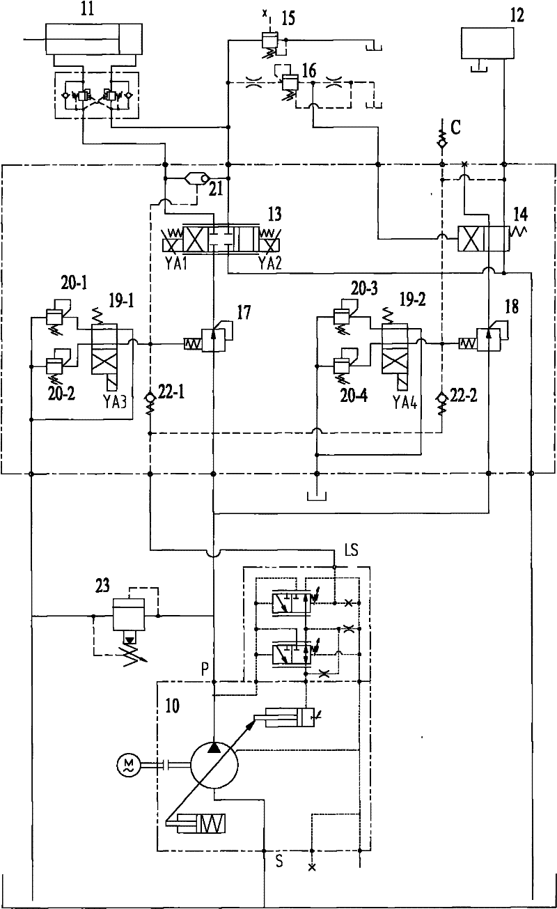
[0044] Please see figure 2 , figure 2 It is a principle schematic diagram of a specific embodiment of the hydraulic control circuit for a rock drill provided by the present invention.

[0045] like figure 2 As shown, the hydraulic control circuit for a rock drill provided by the present invention includes a hydraulic pump 10, a drill rod propulsion cylinder 11, a rock drill 12, a drill rod rotation motor, an electromagnetic reversing valve 13, a reversing valve 14, an unloading valve 15, and a sequence valve 16 . Wherein, the drilling rod rotation motor is not shown in the figure.

[0046] The oil outlet of the hydraulic pump 10 is connected to the oil inlet of the electromagnetic reversing valve 13, the fi...


PUM


Abstract

The invention relates to the technical field of jackdrill and discloses a hydraulic control loop used for jackdrill and control system thereof. The hydraulic control loop used for jackdrill includes a hydraulic pump, a drill rod thrust cylinder, a drill rod spin motor, a solenoid directional valve, a directional valve, an unloading valve and a sequence valve. In the hydraulic control loop used for jackdrill provided by the invention, control valves needing controlling all adopt solenoid valves, and the reversing or flux control of the control valves can be realized by transmitting solenoid control signals to the solenoid valves, and the operation staff do not heed to directly operate the control valves; therefore, the work intensity of the operation staff is smaller, the control performance is good and the defect of inaccurate locating and punching of manual operation can be overcome. One hydraulic pump can simultaneously supply oil to the drill rod thrust cylinder and the jackdrill, can simultaneously implement two motions including boosting and drilling, thus reducing the manufacture cost of the jackdrill. The invention also provides a control system for hydraulic control loop used for jackdrill.

Description

technical field [0001] The invention relates to the technical field of rock drilling machinery, in particular to a hydraulic control circuit for a rock drilling machine, and also relates to a hydraulic control circuit control system for a rock drilling machine. Background technique [0002] The rock drill is a kind of mechanical equipment used for rock drilling. It plays a very important role in the roadway excavation process of underground mines such as coal mines, black and non-ferrous mines, and plays an important role in the mechanization of rock roadway operations. Rock drills can be divided into pneumatic rock drills, internal combustion rock drills, electric rock drills and hydraulic rock drills according to their power sources. [0003] The hydraulic rock drill is a commonly used rock drill. The hydraulic rock drill is mainly powered by a hydraulic pump, and its actuator is controlled by a hydraulic control circuit to perform corresponding actions. The following bri...

Claims


Application Information

Patent Timeline
IPC IPC(8): E21B6/00F15B15/18F15B11/05
Inventor 陈锷牟东刘会永刘宗宏马刚
Owner SANY HEAVY EQUIP
Learn More