Machining method of steel mould cavity

A processing method and model technology, applied in the direction of processing electrodes, electric processing equipment, metal processing equipment, etc., can solve the problems of slow EDM processing speed, difficult to guarantee processing accuracy, loss of tool electrodes, etc., and achieve good electrolysis effect, Low cost, cost reduction effect

Inactive Publication Date: 2010-07-07
CHANGZHOU CHENKAI RAPID MFG TECH
View PDF0 Cites 10 Cited by
  • Summary
  • Abstract
  • Description
  • Claims
  • Application Information

AI Technical Summary

Problems solved by technology

EDM has two fatal disadvantages: one is that EDM belongs to electrical discharge machining, and its tool electrodes are lossy. In order to ensure the accuracy of the mold cavity, it is necessary to use multiple tool electrodes to process the same cavity, that is, It is time-consuming and doubles the cost, and it is difficult to guarantee the processing accuracy; second, the processing speed of EDM is very slow, so cutting processing (including cutting processing by five-coordinate linkage CNC machining center) has to be used to advance Remove most of the stock and then EDM to increase productivity

Method used


Image

  • Machining method of steel mould cavity
  • Machining method of steel mould cavity
  • Machining method of steel mould cavity

Examples


Embodiment 1

[0058] The present invention will be described in detail below in conjunction with a specific embodiment, but the present invention is not limited to this embodiment.

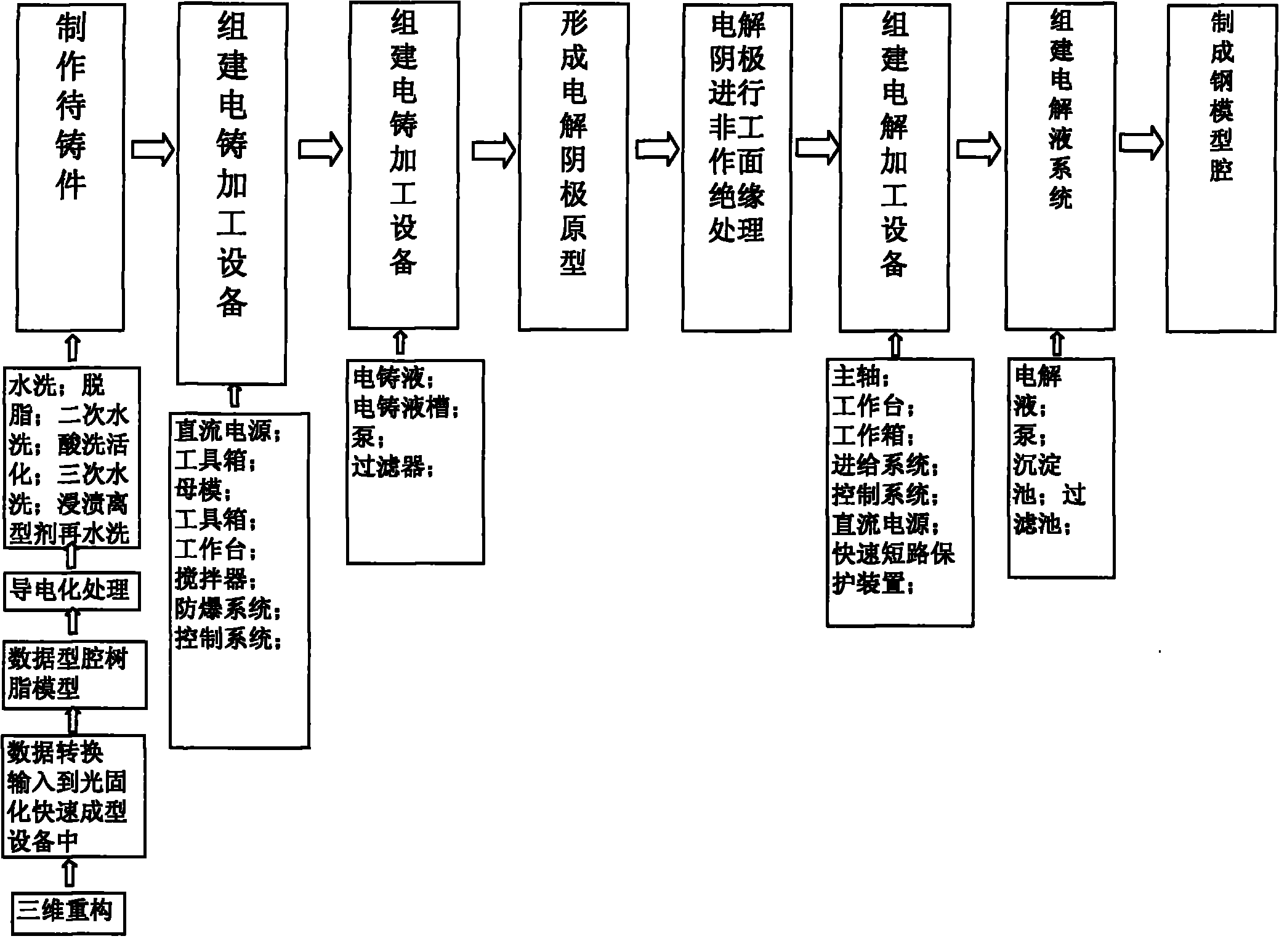
[0059] Taking the processing of stamping dies for aircraft panels as an example, the processing steps are as follows:

[0060] 1) Make the parts to be cast:

[0061] a. Use CAD drawing software to realize the three-dimensional reconstruction of the mold cavity;

[0062] b. Convert the above three-dimensional reconstructed entity data into an STL format file, and generate the default format file of the light-curing rapid prototyping equipment through Rpdata software layered slice processing, and input it into the light-curing rapid prototyping equipment;

[0063]The STL format file is a standard file type used in the rapid prototyping system, such as a common TXT file.

[0064] c. The photocuring rapid prototyping equipment receives the input instruction and manufactures the resin prototype of the required mol...


PUM

PropertyMeasurementUnit
diameteraaaaaaaaaa

Abstract

The invention discloses a machining method of a steel mould cavity. The machining method comprises the four steps of: manufacturing an electrolysis cathode by utilizing the combination of a photocuring rapid prototyping technology and an electrotyping technology, building an electrolysis machining device, building an electrolyte system and forming the steel mould cavity. The machining method has the advantages that: compared with the traditional method for manufacturing an electric spark tool electrode or the electrolysis cathode, the rapid prototyping method for manufacturing the electrolysis cathode saves a cutting machine tool, a numerical control machine tool and properties and has high production efficiency, low cost as well as good precision and surface quality; in addition, the production efficiency of electrolysis machining is high, which is about 5 to 10 times of the electric spark machining and higher than the production efficiency of cutting machining, and the machining production rate is not restricted by the machining precision and the surface roughness; and the invention can reach good surface roughness and machining precision.

Description

technical field [0001] The invention relates to the processing field of cavity moulds, in particular to a processing method for steel mold cavities. Background technique [0002] In today's manufacturing industry, molds (including stamping molds, plastic molds, forging molds, casting molds, metal die-casting molds, powder metallurgy molds, etc.) are important process equipment and an indispensable part to ensure product manufacturing. [0003] Among all kinds of molds, cavity molds of steel (including various special tool steels, alloy steels, and even hard alloys, etc.) are the most difficult to manufacture. With the rapid development of the manufacturing industry, in order to manufacture product parts with complex shapes, high hardness, high strength and strong toughness, the requirements for the precision and surface finish of the mold are getting higher and higher, and the life of the mold is required to be longer and longer. The production cycle is getting shorter and ...

Claims


Application Information

Patent Timeline
Patent Type & Authority Applications(China)
IPC IPC(8): B23H3/00B23H3/04C25D1/00C25D1/10
Inventor 刘延禄陈进刚刘江
Owner CHANGZHOU CHENKAI RAPID MFG TECH
Why Eureka
Try Eureka