Sealing structure of soaking plate and manufacturing method

A manufacturing method and vapor chamber technology, which is applied to heat storage heaters, fluid heaters, heat exchange equipment, etc., can solve problems such as defective vapor chambers, damage, and high manufacturing costs, and achieve good use effects and excellent product performance , The effect of low scrap rate

Active Publication Date: 2010-07-07
ZHONGSHAN WEIQIANG TECH
View PDF0 Cites 8 Cited by
  • Summary
  • Abstract
  • Description
  • Claims
  • Application Information

AI Technical Summary

Problems solved by technology

[0004] Vapor chambers and semi-finished products produced through the above-mentioned steps in the previous section will use a thin metal tube as a reserved liquid injection port during the welding and sealing process. The structure is as follows: figure 2 As shown, 1' is the semi-finished vapor chamber, 2 is the sealing structure, and 3 is a thin metal tube; such a structure is very easy to be damaged by accidental collision during subsequent manufacturing and use, resulting in the vapor chamber becoming a defective product
[0005] Moreover, when performing post-manufacturing steps on the vapor chamber semi-finished product, for the operations of quantitative liquid injection, vacuuming and sealing welding, the existing technical solution is to inject the liquid from the liquid injector into the metal liquid injection pipe on the vapor chamber , after reaching a certain amount of liquid, the liquid injector is removed; then the semi-finished vapor chamber is moved to the next workstation for vacuuming; and then the sealing welding operation is performed, which is time-consuming and labor-intensive. high cost
[0006] In addition, due to the pressure drop due to the high vacuum inside the cavity, using the same opening as the working port for liquid injection and vacuuming, it is easy to cause rapid vaporization of the liquid surface during liquid injection, and a little carelessness will reduce the amount of liquid injected. Insufficient, and thus prone to dry out (dry out) phenomenon

Method used


Image

  • Sealing structure of soaking plate and manufacturing method
  • Sealing structure of soaking plate and manufacturing method
  • Sealing structure of soaking plate and manufacturing method

Examples


Embodiment Construction

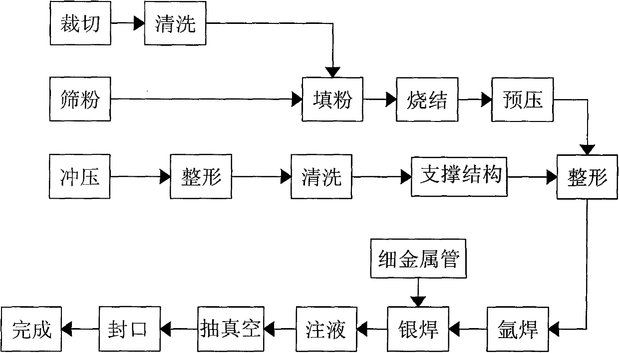
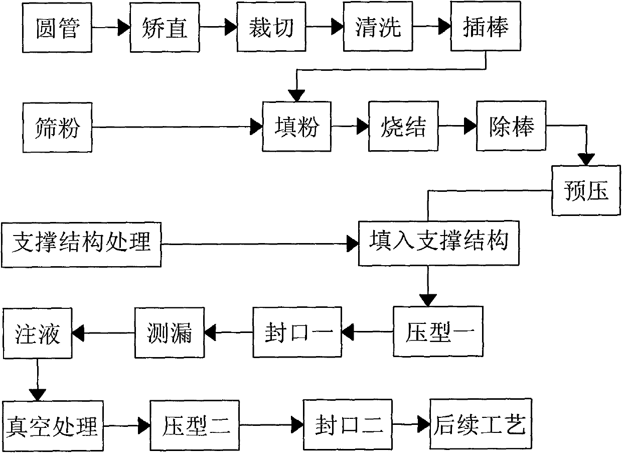
[0027] Please refer to image 3 , is the process flow chart of Embodiment 1 of the method for manufacturing a vapor chamber of the present invention. The metal raw material used in this embodiment is a metal tube, and the process steps include:

[0028] Step 1, raw material preparation: prepare the metal raw material of the vapor chamber, and cut it to a predetermined size; since metal pipes are used as raw materials, there are related operations for metal pipes in this step, and the steps can be subdivided into:

[0029] Step 1.1, cutting: cutting the metal tube to obtain the metal tube raw material of predetermined size; and straightening the metal tube before cutting to ensure the pass rate of the product; cleaning the metal tube after cutting to ensure the quality of the cavity;

[0030] Step 1.2, Insert rod: Insert a mold rod matching the inner diameter of the empty pipe into the cavity of the metal tube, and sinter the mold rod with the raw material powder of the subsequ...


PUM


Abstract

The invention relates to a manufacturing method of a soaking plate, which comprises the following processing steps: preparing raw materials, filling powder and sintering, prepressing, filling into a supporting structure, compressing, sealing, injecting liquid and vacuum treating. A sealing structure of the soaking plate comprises a half-finished product of the soaking plate, a liquid injecting port and a supporting structure, wherein the half-finished product of the soaking plate is provided with a vacuum chamber; the liquid injecting port is positioned at one side of the soaking plate; the supporting structure is arranged in the vacuum chamber and used for supporting the outline of the half-finished product of the soaking plate; the liquid injecting port is an sealing port integrally-formed by pressing and sealing the side of the soaking plate; after sealing, a liquid injecting tube needs not to be welded, but the liquid injecting port is reserved; and after liquid injection, vacuum treating and sealing are carried out. The soaking plate produced by the steps does not need a thin metal tube, can be unified in a vacuum box for carrying out the subsequent sealing processes, and avoids the unfavorable condition caused by the internal and external pressure difference of the chamber of the soaking plate, so that the produced product has good performance, low rejection rate and good use effect.

Description

technical field [0001] The invention relates to a heat soaking plate, in particular to a sealing structure of a heat soaking plate and a manufacturing method thereof. Background technique [0002] The vapor chamber is a high-performance heat dissipation device, which is mostly used in high-performance electronic components. Its basic structure is a shell with a vacuum chamber, and a microstructure is arranged in the chamber, and it is filled with a working liquid. The suction and heat dissipation caused by solidification and evaporation and the capillary force of the microstructure to the working liquid conduct heat conduction; the structure of the vapor chamber requires an internal vacuum. The existing chamber manufacturing technology, whether it is the inner cavity formed by the upper and lower covers, Or the inner cavity formed by the copper tube through pressing, the production steps are as follows figure 1 As shown, all include: the steps of powder filling and sinterin...

Claims


Application Information

Patent Timeline
Patent Type & Authority Applications(China)
IPC IPC(8): B23P15/26B22F7/00B21D53/04F28D15/04
CPCF24H7/00B22F3/1258B22F7/08
Inventor 李克勤
Owner ZHONGSHAN WEIQIANG TECH
Why Eureka
Try Eureka