Microaerophilic recirculation treatment method for membrane-separation concentrated solution of garbage leachate

A technology of landfill leachate and treatment method, which is applied in the field of micro-aerobic recharge treatment, which can solve the problems of increased concentration and unfavorable treatment, and achieve the effects of accelerated removal, favorable degradation and stability, and accelerated waste degradation

Inactive Publication Date: 2010-07-07
GUANGXI UNIV
View PDF0 Cites 14 Cited by
  • Summary
  • Abstract
  • Description
  • Claims
  • Application Information

AI Technical Summary

Problems solved by technology

[0007] 2. With the increase of recharge time, the settlement rate of the landfill layer slows down, and the porosity gradually decreases, resulting in insufficient oxygen to affect the nitrification reaction. With the increase of t

Method used


Image

  • Microaerophilic recirculation treatment method for membrane-separation concentrated solution of garbage leachate
  • Microaerophilic recirculation treatment method for membrane-separation concentrated solution of garbage leachate
  • Microaerophilic recirculation treatment method for membrane-separation concentrated solution of garbage leachate

Examples


Embodiment 1

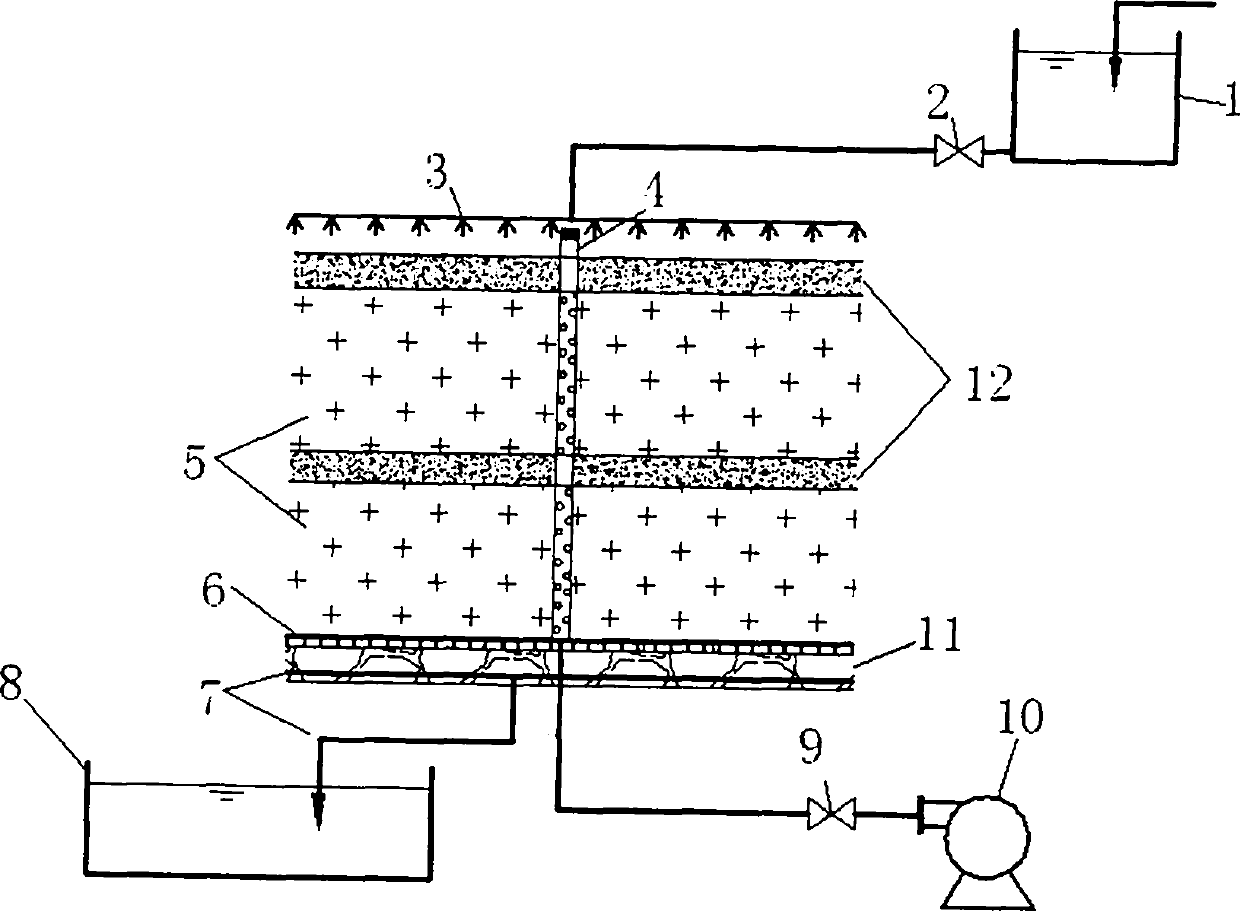
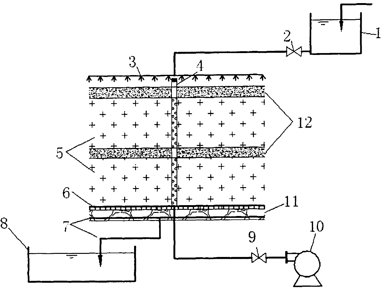
[0031] Test device such as figure 1As shown, a Φ350×700mm cylinder is used to simulate the landfill unit of leachate recharge. The device is filled with 60Kg of garbage, which comes from the municipal garbage transfer station. A covering soil layer with a thickness of 50 mm is set up at the top and middle of the recharging area respectively. The recharge concentrated liquid is adjusted from the head tank 1 through the liquid inlet valve 2 to adjust the hydraulic load, and is evenly sprayed on the surface layer of the landfill through the water distribution pipe 3. The concentrated liquid seeps twice through the covering soil layer 12 and the landfill layer 5 in order to carry out organic pollution. After the synergistic effects of filtering and intercepting, physical adsorption, chemical deposition, biodegradation, etc., the water finally flows into the drainage collection pipe 7 at the bottom and flows to the leachate stabilization pond 8. The air blower 10 distributes the ...

Embodiment 2

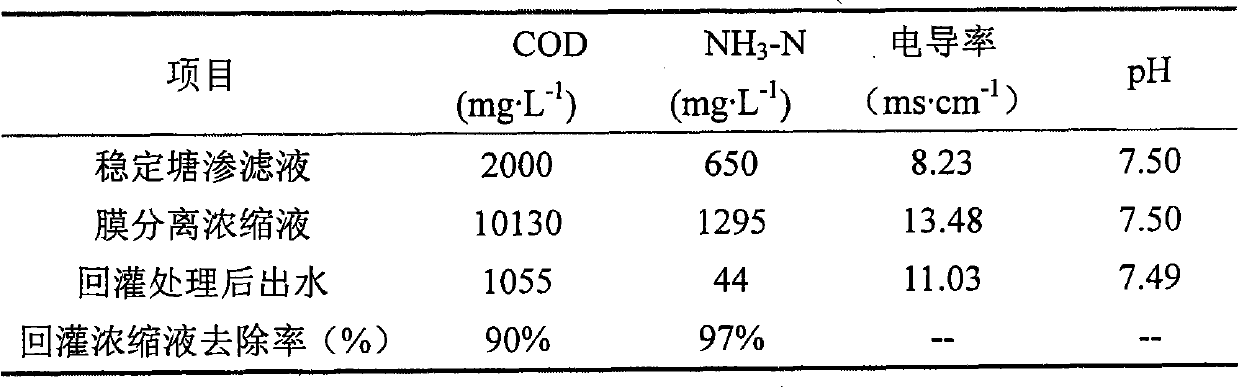
[0035] Others are the same as in Example 1, except that the initial hydraulic load of refilling is controlled at 12.5mL / (L·d), and the gas supply is controlled at 0.06L / (min·kg); when the effluent COD drops below 4000, the NH 3 When -H drops below 400, the hydraulic load is controlled at 37.5mL / (L·d), and the gas supply is controlled at 0.10L / (min·kg). The specific test data are as follows:

[0036]

Embodiment 3

[0038] Others are the same as in Example 1, except that the initial recharge frequency: 3 times / d; middle and late recharge frequency: 2 times / d. The specific test data are as follows:

[0039]


PUM


Abstract

The invention relates to a microaerophilic recirculation treatment method for a membrane-separation concentrated solution of garbage leachate, which comprises the following steps: the concentrated solution is uniformly distributed on the surface layer of the recirculation area via an overhead tank and water distribution pipes, and discharged into a drain pipe via an overlaid soil layer, a garbage landfill layer and a pebble layer; and a forced draft is introduced into the recirculation area to accelerate the organic matters in the concentrated solution and garbage to decompose, and the concentrated solution is finally discharged into a stabilization pond. Since the landfill layer provides a microaerophillic environment, acid fermentation, high concentration and organic acid accumulation are inhibited, thereby accelerating the removal of COD and NH3-N; and the abundant microbial populations in the landfill layer is beneficial to the degradation and stabilization of the landfill layer. Thus, the invention has strong capability for resisting hydraulic load variations and favorable recirculation treatment effect on the concentrated solution.

Description

technical field [0001] The invention belongs to a method for micro-aerobic recharge treatment of landfill leachate membrane separation concentrated liquid. Background technique [0002] At present, my country's urban domestic waste is mainly treated by sanitary landfill. A large amount of landfill leachate produced during the landfill process has high organic concentration, complex components, and many toxic and harmful substances. Traditional anaerobic + aerobic biological treatment, supplemented by activated carbon adsorption , Chemical precipitation, chemical oxidation and other physical and chemical methods for advanced treatment, it is difficult to meet the discharge requirements of the "Standards for Pollution Control of Landfill of Domestic Waste" GB16889-2008. The main reason is that the concentration of ammonia nitrogen in the landfill leachate is too high and the biodegradability is poor, especially in the dry season and the later stage of landfill, the concentratio...

Claims


Application Information

Patent Timeline
IPC IPC(8): C02F3/30
Inventor 冼萍郭健邓超冰吴家前李丽和
Owner GUANGXI UNIV
Why Eureka
Try Eureka