Vertical drying shed and drying method
A drying room and air duct technology, applied in the direction of drying solid materials, drying gas arrangement, local agitation dryers, etc., can solve the problems of large space occupation, poor effect, incompatible production line, etc., to improve the utilization rate of heat, The overall structure is compact and convenient for batch drying
- Summary
- Abstract
- Description
- Claims
- Application Information
AI Technical Summary
Problems solved by technology
Method used
Image

Examples
Embodiment 1
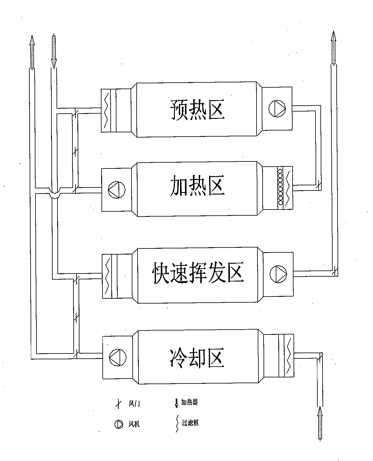
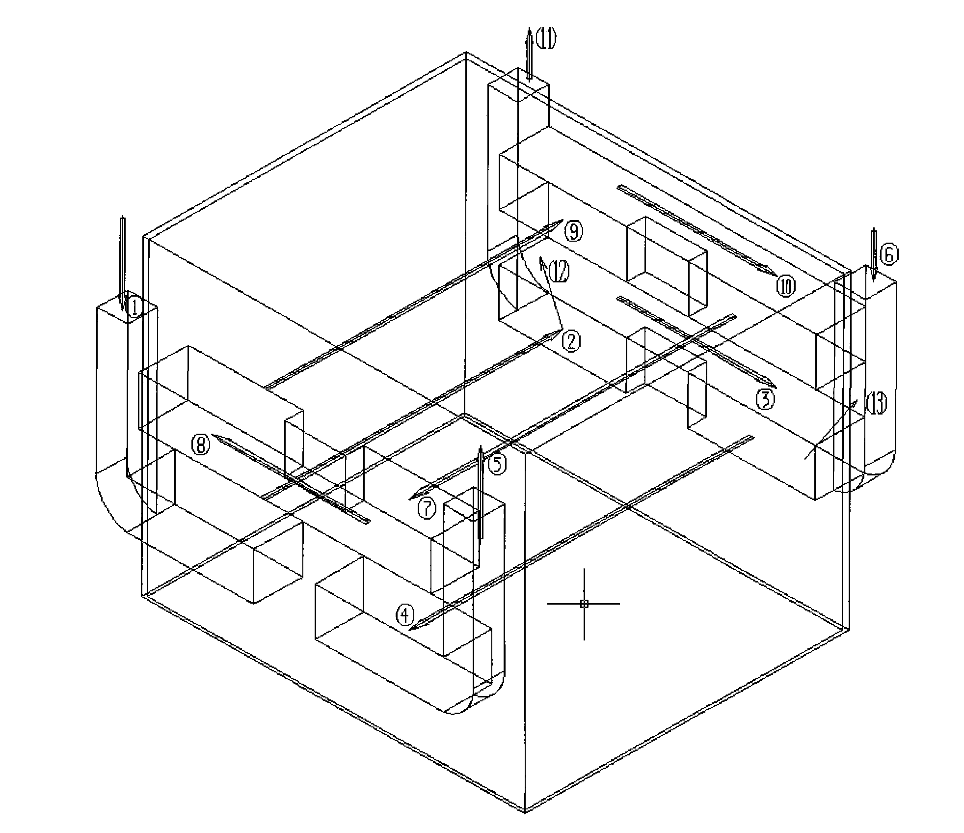
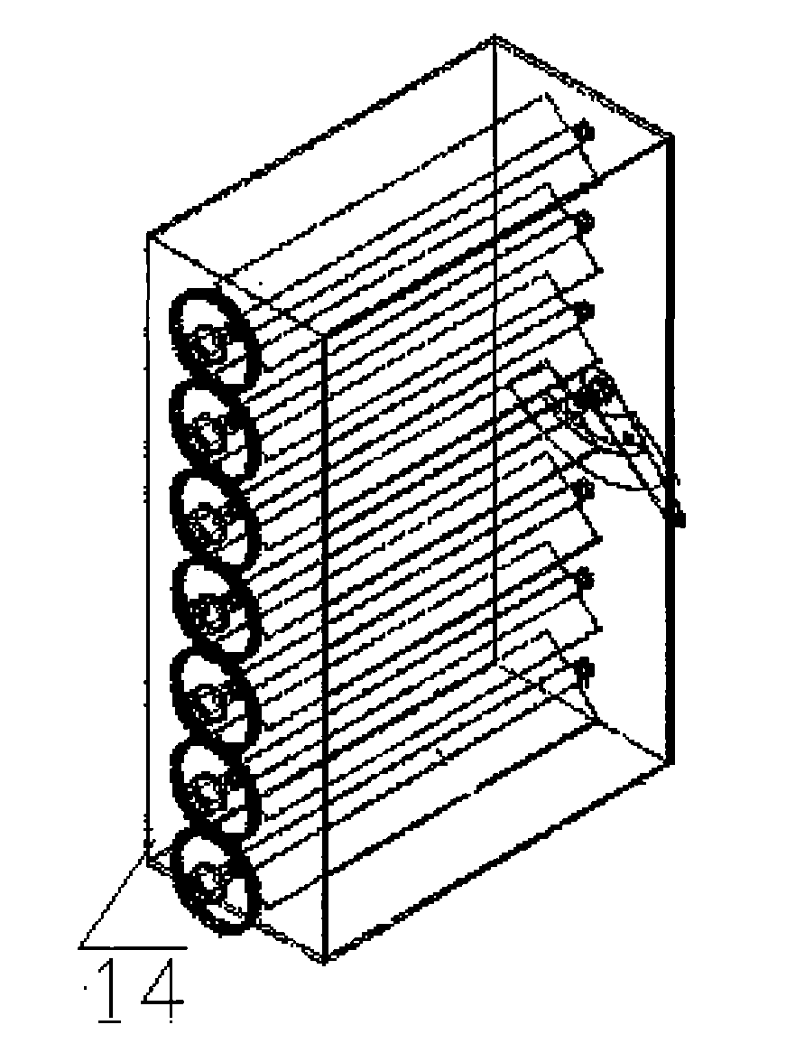
[0012] Embodiment 1: with reference to attached Figure 1~3 . Vertical drying room, which includes a drying room. The drying room is sealed by a polyurethane composite plate, with doors at the four corners. The inside of the plate is galvanized and the base is completely sealed. Zone, heating zone, cooling zone, a heating fan 9 and a cooling fan 2 are arranged on one side of the confined space, and the heating fan 9 is located on the upper part of the cooling fan 12, and the heating zone air outlet 11 is arranged on the side near the heating fan, and on the other side One side is provided with the upper tuyere 6 of the preheating zone, and is connected with the heating blower 9 and the cooling blower 12 through connecting the air passage 10 and the air passage 3 respectively, and the opposite side of the heating blower 9 is provided with a heater 8 and an air passage, and the heating The device 8 is located on the top of the air duct 1, the air duct 1 is L-shaped, and the hea...
Embodiment 2
[0015] Embodiment 2: On the basis of Embodiment 1, the drying method of the vertical drying room, the paint drying process is divided into a fast volatilization zone, a preheating zone, a heating zone, and a cooling zone. In the first link of spraying wet materials into the working environment Blow the surface of the wet paint containing a large amount of solvent through the high-speed air flow at room temperature to promote a large amount of paint solvent to volatilize rapidly, prevent the foaming phenomenon caused by the rapid temperature rise in the heating zone, the paint begins to solidify and the solvent expands, and ensure the drying quality; use The circulation transport mechanism of the tray sends the wet material vertically into the preheating zone, and under the condition of hot air at a certain temperature, it gradually meets the appropriate physical conditions for paint curing and solvent volatilization; after preheating, in order to facilitate the full use of heat ...
PUM
 Abstract
Description
Claims
Application Information
 - R&D
- Intellectual Property
- Life Sciences
- Materials
- Tech Scout
- Unparalleled Data Quality
- Higher Quality Content
- 60% Fewer Hallucinations
Browse by: Latest US Patents, China's latest patents, Technical Efficacy Thesaurus, Application Domain, Technology Topic, Popular Technical Reports.
© 2025 PatSnap. All rights reserved.Legal|Privacy policy|Modern Slavery Act Transparency Statement|Sitemap|About US| Contact US: help@patsnap.com