Cooling method used for directional solidification and cooling device therefor

A technology of directional solidification and cooling method, applied in the field of spray cooling devices, can solve the problems of slow cooling rate, complex production conditions, high cooling rate and other problems of single crystal, and achieve the effect of large temperature gradient, large temperature gradient and not easy to vaporize

Inactive Publication Date: 2010-07-28
SHANGHAI UNIV
View PDF4 Cites 24 Cited by
  • Summary
  • Abstract
  • Description
  • Claims
  • Application Information

AI Technical Summary

Problems solved by technology

Due to the slow cooling rate of single crystal, complex production conditions and high cost, polycrystals are mostly used in actual production, especially in the case of obtaining parallel columnar crystals, a high cooling rate is required to extract heat as soon as possible; at this time Conventional air-cooling or water-cooling methods cannot meet the requirements

Method used


Image

  • Cooling method used for directional solidification and cooling device therefor
  • Cooling method used for directional solidification and cooling device therefor
  • Cooling method used for directional solidification and cooling device therefor

Examples


Embodiment 1

[0034] Embodiment one: see figure 1 and figure 2 , This cooling method for directional solidification uses liquid metal as the cooling liquid, and the mold shell is sprayed alone, or the spray cooling method and the immersion cooling method are carried out at the same time.

Embodiment 2

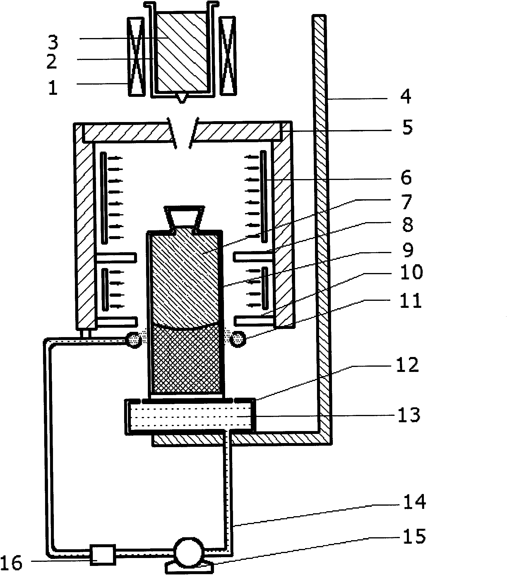
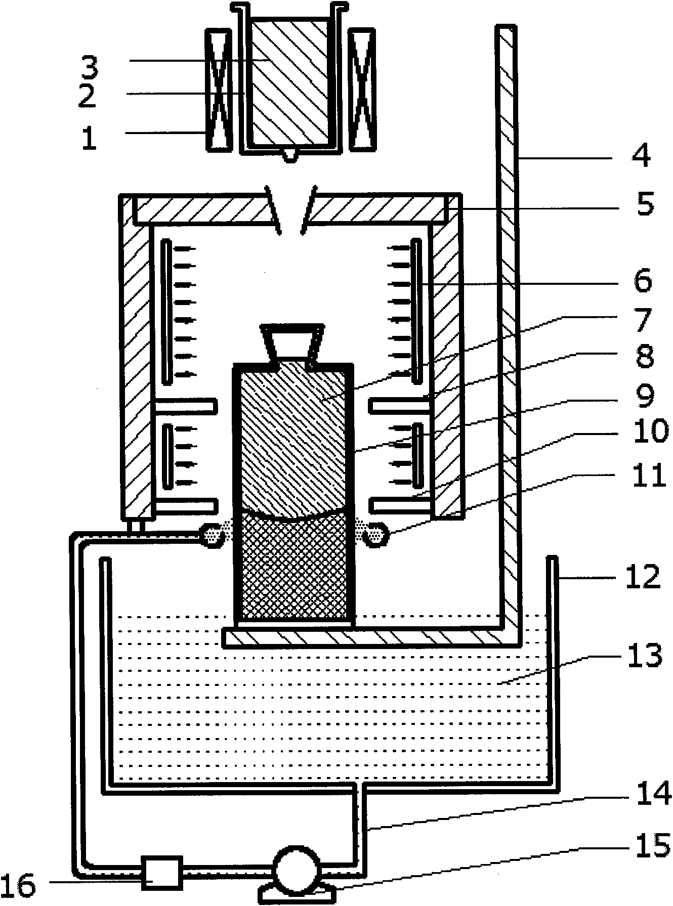
[0035] Embodiment two: if figure 1 As shown, the immersion cooling device used for directional solidification includes a melting furnace 2 with a heating coil 1, a holding furnace 5, a mold shell 9 and a liquid reservoir 12, and the upper cover of the holding furnace 5 has a pouring The smelting furnace 2 with the heating coil 1 is arranged above the pouring port, the liquid outlet at the bottom of the smelting furnace 2 is aligned with the pouring port on the upper cover of the holding furnace 5, and the inner chamber of the holding furnace 5 It can accommodate the formwork 9, and there is an upper heat insulation board 8 in the middle of the inner cavity to divide the inner cavity of the holding furnace 5 into an upper heating zone 6 and a lower heating zone. There is a lower heat insulation board 10; an annular nozzle 11 is arranged on the lower edge of the holding furnace 5, and the annular nozzle 11 is connected to the outlet of the pump 15 through a cooling system 16, an...

Embodiment 3

[0036] Embodiment three: see figure 1 , the technical process of the immersion cooling method for directional solidification is as follows: the heating coil 1 in the melting furnace 2 melts the solid superalloy 3, and then injects it into the mold shell 9 in the holding furnace 5; after the pouring is completed, the mold shell 9 Move down with the drawing device 4, and immerse in the cooling liquid 13 at the lower part to cool down, so that the temperature gradient inside the mold shell 9 is always upward; at the same time, the annular nozzle 11 starts to work, spraying the cooling liquid 13 around the mold shell, because the cooling liquid 13 is distributed in a ring shape, so it can effectively isolate the heat radiation between the heating zone and the cooling zone; the mold shell moves downward, the heat is absorbed by the cooling liquid on the lower part and the side wall, and the overall temperature gradient is vertically upward, making the melting Superalloy 7 is gradua...


PUM


Abstract

The invention relates to a cooling method used for directional solidification and a cooling device therefor. In the method, liquid metal is taken as cooling liquid, and a formwork is cooled by adopting the spray cooling method independently or adopting the spray cooling method and the immersion cooling method simultaneously. For the cooling device, a liquid metal spraying device is arranged under a direction solidification holding furnace, and the liquid metal is taken as the cooling liquid to cool the pull-down formwork by spraying independently or accompanying with the immersion. The invention has the advantages that the thermal radiation of a heating area and a cooling area for direction solidification can be insulated; and the cooling liquid is recycled, so as to cool the cooling liquid in cycling.

Description

technical field [0001] The invention relates to a spray cooling device, in particular to a cooling method and device for directional solidification. Background technique [0002] Directional solidification is a process in which metals (or crystalline materials) can solidify or crystallize along a fixed growth direction under the conditions of controlling heat transfer, mass transfer and flow inside the casting. The microstructure of metals after directional solidification is characterized by a group of parallel columnar grains parallel to the direction of solidification heat flow. If the growth process of grains can be properly controlled, such as inhibiting external nucleation, the crystals can grow into a crystalline structure with only one grain, called as a single crystal. [0003] In the production process, the temperature gradient at the front of the solid-liquid interface is the key, and the temperature gradient is directly affected by the cooling rate. It has an imp...

Claims


Application Information

Patent Timeline
Patent Type & Authority Applications(China)
IPC IPC(8): B22D27/04
Inventor 任忠鸣雷作胜王冠邓康任维丽钟云波王敏
Owner SHANGHAI UNIV
Why Eureka
Try Eureka