Method and device for measuring thickness of the center of confocal lens

A central thickness, confocal lens technology, applied in the direction of measuring devices, optical devices, instruments, etc., to achieve high stability, fast measurement speed, and improve the effect of measurement accuracy

Inactive Publication Date: 2010-07-28
BEIJING INSTITUTE OF TECHNOLOGYGY +1
View PDF7 Cites 31 Cited by
  • Summary
  • Abstract
  • Description
  • Claims
  • Application Information

AI Technical Summary

Problems solved by technology

[0013] The purpose of the present invention is to solve the problem of non-contact high-precision measurement of lens ce

Method used


Image

  • Method and device for measuring thickness of the center of confocal lens
  • Method and device for measuring thickness of the center of confocal lens
  • Method and device for measuring thickness of the center of confocal lens

Examples


Embodiment 1

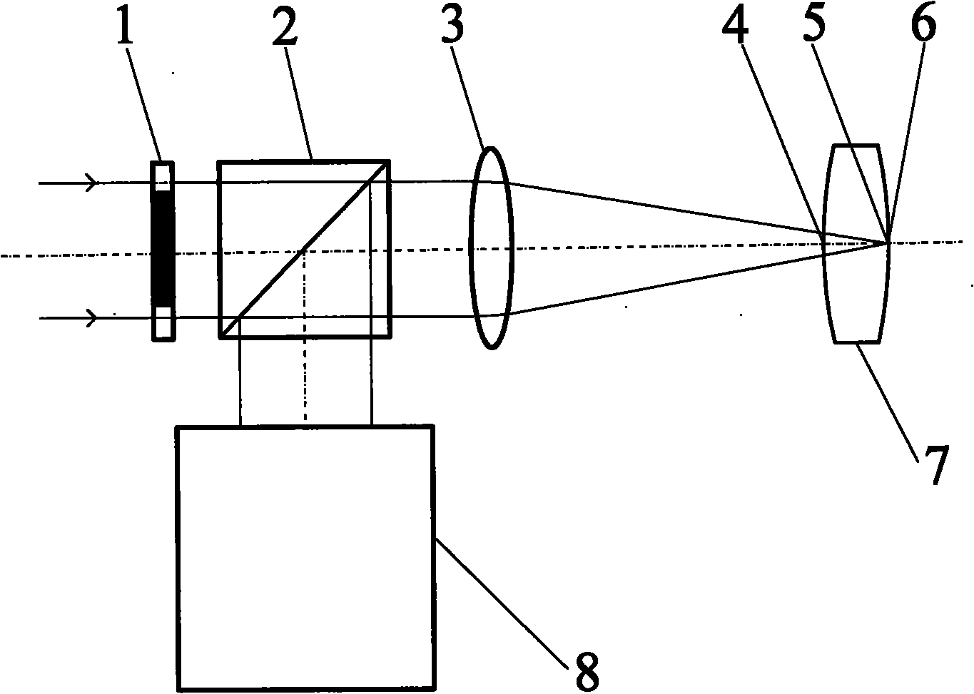
[0051] Such as figure 2 , Figure 5 with Figure 7 As shown in the method for measuring the thickness of the center of the confocal lens, the measurement steps are:

[0052] First, start the measurement software in the main control computer (24), input relevant parameters, including the radius of curvature r of the front surface of the measured lens (7) 1 =90.7908mm, air refractive index n 0 =1 and the measured lens (7) refractive index n=1.5143.

[0053] Then, turn on the collimated light source (17), the parallel light emitted by it passes through the annular pupil (1) with a light transmission diameter of 6.8mm-9.6mm, passes through the beam splitting system (2), and passes through the 35mm objective lens (3) with a top focal length Converge at the focal point and form a hollow light cone at the same time. After the light is reflected by the surface of the measured lens (7), it is reflected again through the objective lens (3) and the beam splitting system (2) and ente...

Embodiment 2

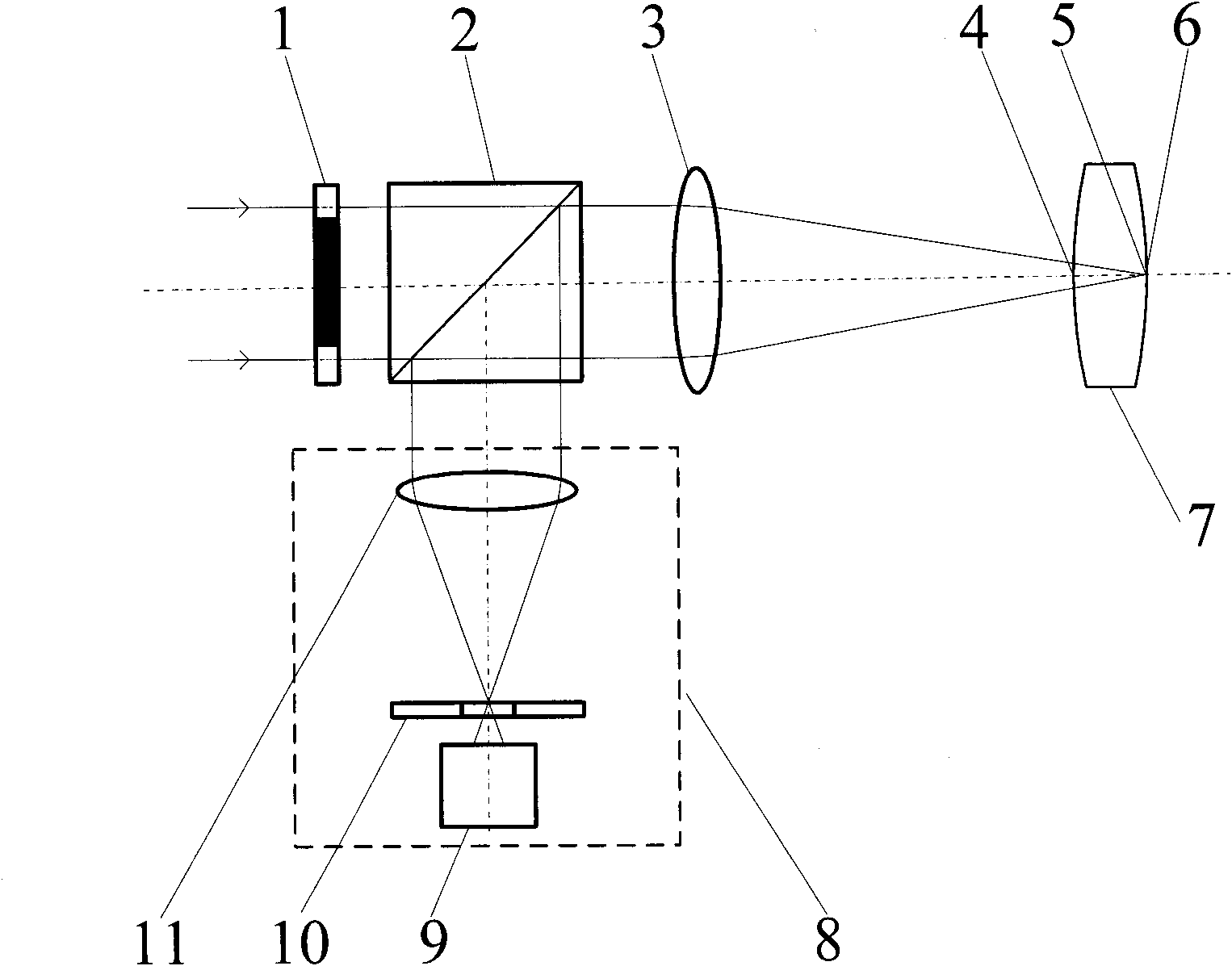
[0063] Such as image 3 , Figure 5 with Figure 7 As shown, the embodiment one figure 2 The confocal system in (8) is replaced by image 3 The confocal system (8) in can constitute the second embodiment. The difference from Embodiment 1 is that the light rays enter the confocal system (8) and converge through the lens (13), and the confocal response signal is directly detected by the CCD detector (12) at the focal point of the lens. The remaining measurement methods and devices are the same as those in Example 1.

Embodiment 3

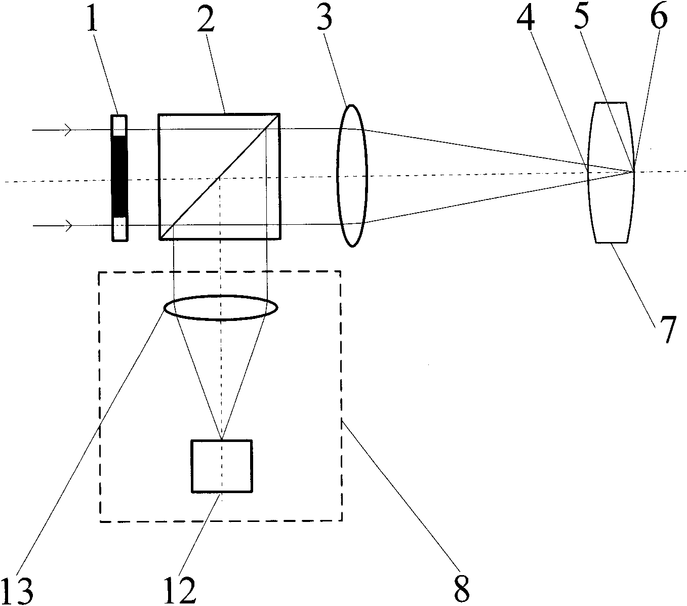
[0065] Such as Figure 4 , Figure 5 with Figure 7 As shown, the embodiment one figure 2 The confocal system in (8) is replaced by Figure 4 The confocal system (8) in can constitute the third embodiment. The difference from Embodiment 1 is that after the light enters the confocal system (8), it is imaged on the surface of the CCD detector (15) through the lens (16) and the microscope objective lens (14), and is detected by the CCD detector (15). focal response signal. The remaining measurement methods and devices are the same as those in Example 1.

[0066] This embodiment realizes the non-contact high-precision measurement of the lens center thickness through a series of measures, and realizes the method and device for measuring the center thickness of the confocal lens, which has the advantages of no damage to the measured lens, high measurement accuracy, long working distance, and Convenience and other advantages.


PUM


Abstract

The invention belongs to the technical field of optical precision measurement, relating to a method and a device for measuring the thickness of the center of a confocal lens. The method comprises the following steps of: first respectively determining the positions of the front surface vertex and the back surface vertex of a lens according to the confocal focusing principle; obtaining first two position coordinates of locations by confocal measurement; and calculating the thickness of the center of the lens by utilizing the ray tracing formula. Meanwhile, an annular pupil is introduced to a measurement optical path to block paraxial rays and form a hollow measuring light cone, thereby reducing the effect of aberration on measurement results. The device comprises a light dividing system, an objective lens, a confocal system, a length measurement system and a movable guideway, wherein the light dividing system, the objective lens and the measured lens are sequentially arranged in the direction of emergent ray of a collimation light source; and the confocal system is arranged in the reflection direction of the light dividing system. The surface of the measured lens and the light dividing system reflect light to the confocal system and cooperate with the confocal system to realize accurate positioning of the front surface vertex and the back surface vertex of the measured lens, so that non-contact precision measurement of the thickness of the center of the lens is realized.

Description

technical field [0001] The invention belongs to the technical field of optical precision measurement and can be used for non-contact high-precision measurement of lens center thickness. technical background [0002] In the field of optics, the measurement of lens center thickness is of great significance. Lens center thickness is an important parameter in the optical system, and its processing quality will have a great impact on the imaging quality of the optical system. Especially for lenses in high-performance optical systems such as lithography objective lenses and aerospace cameras, it is necessary to precisely adjust the axial gap, radial offset and optical axis deflection angle of the lens according to the curvature radius, refractive index and central thickness of the lens in the lens. adjustment. Taking the objective lens of lithography machine as an example, the deviation of the center thickness of each single lens will cause the aberration of the lithography obje...

Claims


Application Information

Patent Timeline
IPC IPC(8): G01B11/06
Inventor 赵维谦刘文丽定翔李飞孙若端邱丽荣史立波杨佳苗
Owner BEIJING INSTITUTE OF TECHNOLOGYGY
Why Eureka
Try Eureka