
Manufacturing method for integral LED light source module

A technology of LED light source and manufacturing method, which is applied in the field of LED, can solve the problems of difficulty in uniform coating of phosphor powder, difficulty in uniformity and control of color temperature, high cost of production and materials, etc., so as to facilitate the packaging of light efficiency and improve the market The effect of competitiveness, ease of testing

Inactive Publication Date: 2010-08-04
林柏廷
View PDF0 Cites 13 Cited by
  • Summary
  • Abstract
  • Description
  • Claims
  • Application Information

AI Technical Summary

Problems solved by technology

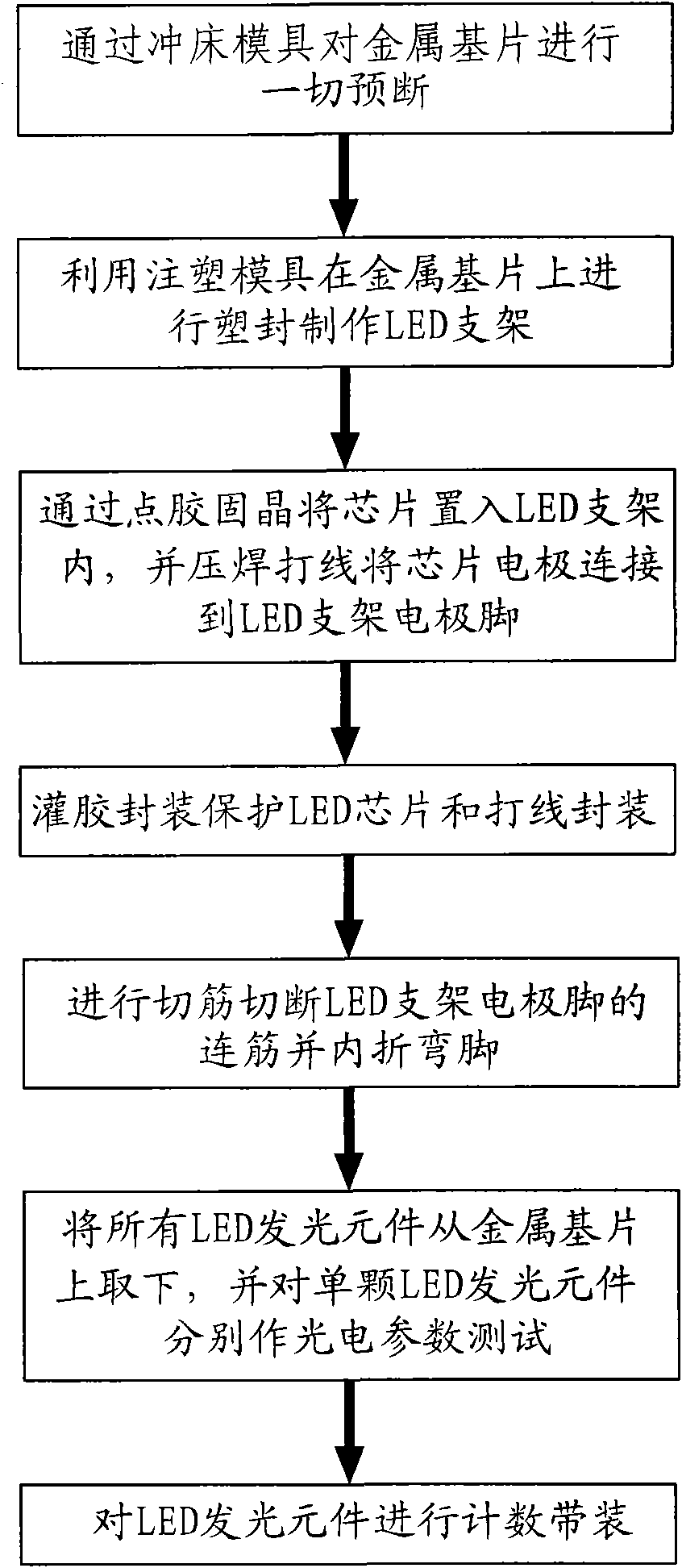
The above-mentioned entire production process is complicated, and the production and material costs are high. The substrate board used to make the LED light-emitting element can only be used as a disposable product, and it will be discarded after taking out the LED light-emitting element, resulting in a lot of waste of resources.
If the COB method is used, it is difficult to uniformize the coating of phosphor powder on the chip, and its light effect and color temperature are difficult to be consistent and controlled.

Method used


Image

  • Manufacturing method for integral LED light source module
  • Manufacturing method for integral LED light source module
  • Manufacturing method for integral LED light source module

Examples


Embodiment Construction

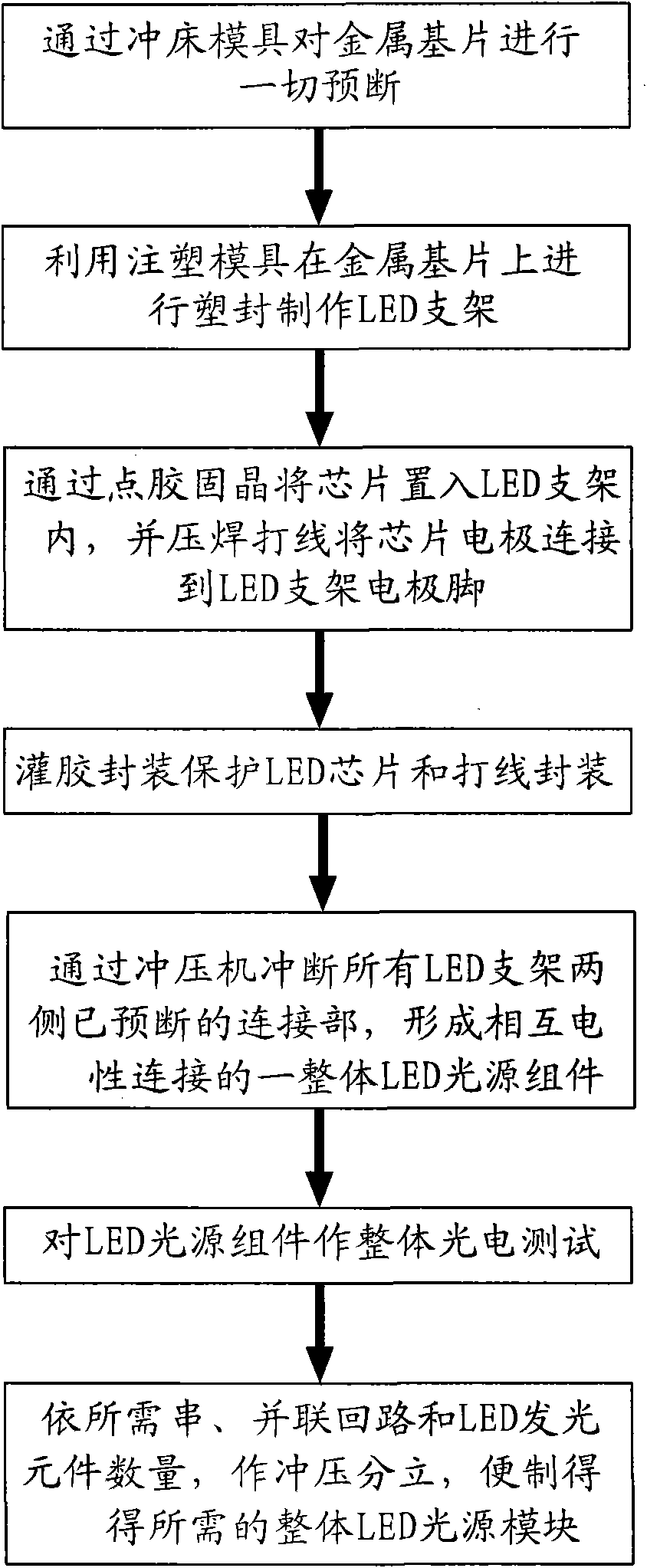
[0020] refer to figure 2 and combine image 3 and Figure 4 . A method for manufacturing an integral LED light source module of the present invention comprises the following process steps:

[0021] a) Carry out all pre-cutting of the metal substrate through the punch die;

[0022] b) Utilize the injection mold to carry out plastic sealing on the metal substrate to make the LED bracket;

[0023] c) Put the chips into the LED bracket one by one by dispensing glue and solidifying the crystal, and connect the chip electrode to the electrode pin of the LED bracket with an aluminum wire or gold wire welding machine through pressure welding;

[0024] d) Refilling package protects LED chip and aluminum wire or gold wire package

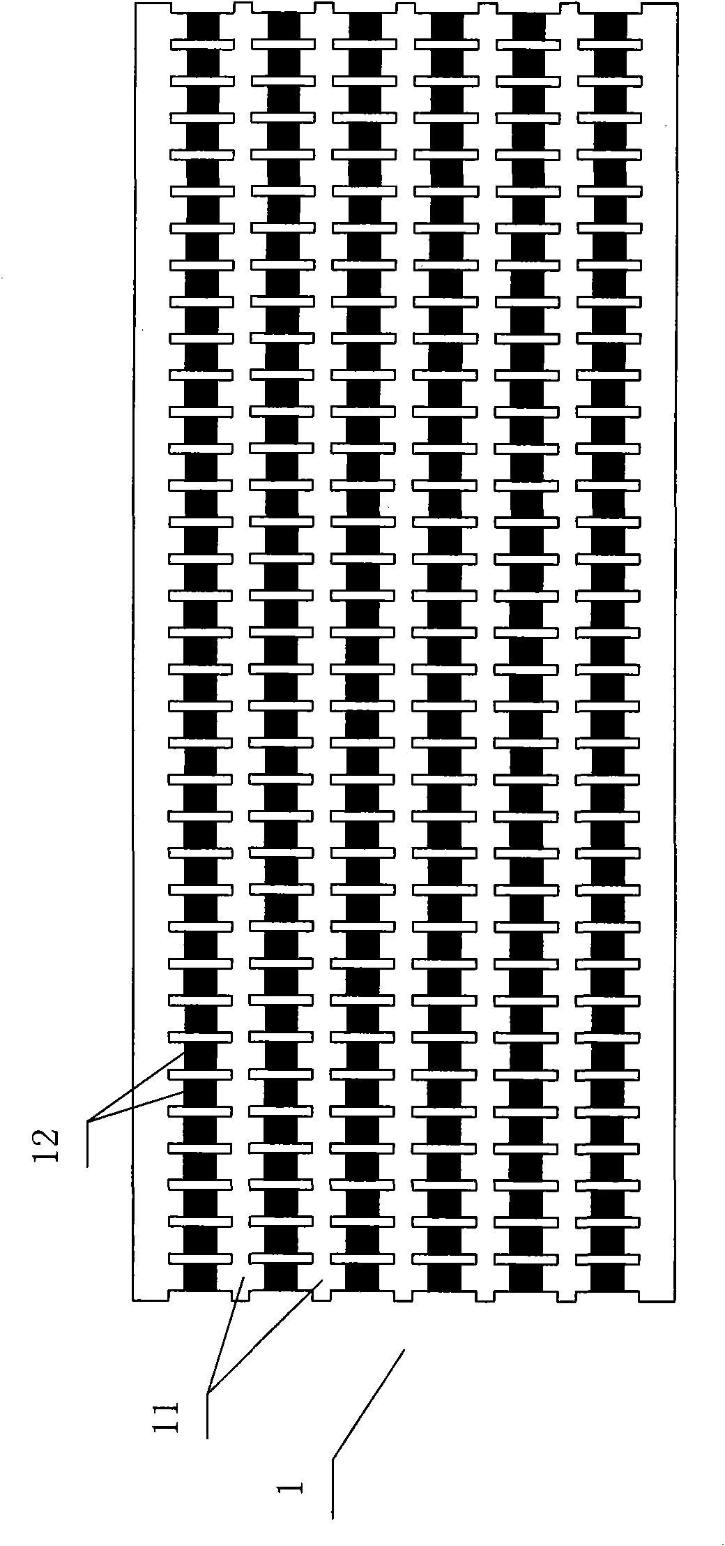
[0025] e) Next, use a punching machine to punch out the pre-broken connection parts on both sides of all LED brackets to form image 3 and Figure 4 An integral LED light source assembly 1 in which all LED light-emitting elements 11 shown in are elect...


PUM


Abstract

The invention relates to a manufacturing method for an integral LED light source module. The manufacturing method comprises the following technological steps that: a metal substrate is precut; an LED support is manufactured on the metal substrate through plastic encapsulation; chips are placed in the LED support one by one through adhesive dispensing and die bonding, and the electrodes of the chips are connected with the electrode pin of the LED support through pressure welding and routing; adhesive is injected to encapsulate and protect the LED chips and the routing; precut connecting parts on the two sides of the LED support are punched to be cut to form an integral LED light source assembly; an integral test is conducted to all LED light emitting elements; and finally punching discretion is conducted to obtain the required integral LED light source module according to the required series and parallel circuits and the number of the LED light emitting elements. The invention properly uses the metal substrate as the base material, uses high-reflectivity plastics to be combined with the metal substrate for series and parallel circuit connection to manufacturing the integral LED light source module, omits the manufacturing process of pin bending and semi-discretion and the tape armoring and the manufacturing process of the existing SMT on the basis of the existing SMD manufacturing process, and greatly shortens the manufacturing process of the elements.

Description

technical field [0001] The invention relates to the technical field of LEDs, in particular to a method for manufacturing an integral LED light source module. Background technique [0002] At present, a general LED light source module consists of several LED chips welded on the substrate by patch or plug-in. The power of a single LED light-emitting element is 0.03-5W. The substrate is a PCB board, a flexible PCB board or aluminum, copper, etc. Metal substrates made of metal materials; or LED chips directly packaged on various substrates, commonly known as COB (chips on board). The above-mentioned substrates for fixing LED chips are designed with a heat dissipation structure, usually an aluminum substrate plus an aluminum profile heat sink, plus natural heat dissipation, air cooling or heat pipe heat dissipation, and semiconductor refrigeration for heat dissipation. [0003] figure 1 The production process of LED light-emitting components is given in , the main steps include...

Claims


Application Information

Patent Timeline
Patent Type & Authority Applications(China)
IPC IPC(8): F21S2/00F21V19/00F21V21/00F21V23/00F21V29/00H01L33/00F21Y101/02F21V29/85
Inventor 林柏廷
Owner 林柏廷
Learn More