
Liquid crystal adaptive aberration correction retinal imaging device with high-efficiency utilization of energy

A liquid crystal self-adaption and aberration correction technology, which is applied in applications, eye testing equipment, medical science, etc., can solve problems such as large energy loss, achieve the effects of increasing universality, reducing costs, and solving sensitivity limitations

Inactive Publication Date: 2010-08-11
CHANGCHUN INST OF OPTICS FINE MECHANICS & PHYSICS CHINESE ACAD OF SCI
View PDF0 Cites 23 Cited by
  • Summary
  • Abstract
  • Description
  • Claims
  • Application Information

AI Technical Summary

Problems solved by technology

[0005] At present, there are 4 Chinese invention patents mentioning that the retinal adaptive correction imaging system can use a liquid crystal corrector (Zhang Yudong, et al., Chinese invention patents: adaptive optics retinal imaging system, ZL99115053. .x), two of the patents adopt a common optical path design, and a 1 / 4 wavelength plate is placed before the corrector, so that the light incident on the corrector is circularly polarized light. In fact, the liquid crystal corrector cannot work in circularly polarized light The other two patents are not aimed at the optimized design of the liquid crystal corrector. The beam splitter placed in front of the human eye will lose half the light intensity emitted by the human eye, which may be possible for a liquid crystal corrector system with a large energy loss. is a fatal flaw

Method used


Image

  • Liquid crystal adaptive aberration correction retinal imaging device with high-efficiency utilization of energy
  • Liquid crystal adaptive aberration correction retinal imaging device with high-efficiency utilization of energy
  • Liquid crystal adaptive aberration correction retinal imaging device with high-efficiency utilization of energy

Examples


Embodiment Construction

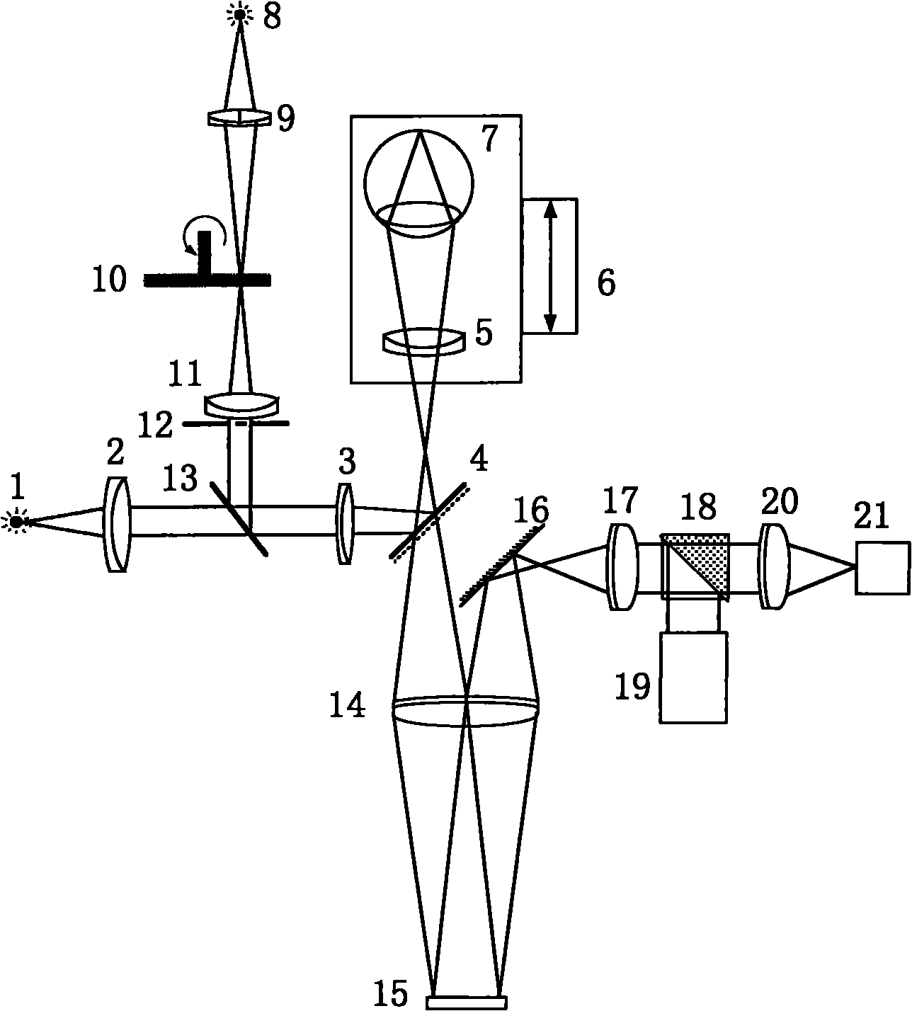
[0017] 1) A light-emitting diode with a luminous wavelength λ' of 550 nm is used as the light source 1 for the visual mark.

[0018] 2) The illumination source 8 used is a small semiconductor laser with fiber coupling, the core diameter is 100 μm, the emission wavelength λ is 808 nm, and the output power is adjustable in the range of 10 mW to 20 mW.

[0019] 3) The beam splitter 4 used has a transmittance ratio of about 4 for the fundus illumination light with a wavelength of 808nm.

[0020] 4) The first lens 2, the second lens 3, the third lens 5, the fourth lens 9, the fifth lens 11, the sixth lens 14, the seventh lens 17, and the eighth lens 20 are double cemented achromatic lenses, and The surface is coated with anti-reflection coating. The calibers are: 20mm, 25mm, 25mm, 10mm, 20mm, 40mm, 20mm, 20mm; the focal lengths are: 50mm, 250mm, 200mm, 30mm, 50mm, 250mm, 86mm, 100mm.

[0021] 5) Select the human eye 7 as 800 degrees of myopia and 150 degrees of astigmatism, and i...


PUM

PropertyMeasurementUnit
Luminous wavelengthaaaaaaaaaa
Diameteraaaaaaaaaa
Thicknessaaaaaaaaaa

Abstract

The invention belongs to the technical field of adaptive optical imaging, and relates to an optical design of high resolution imaging of fundus oculi retina, which is a liquid crystal adaptive aberration correction retinal imaging device with high-efficiency utilization of energy. The imaging device is characterized in that a polarizing beam splitter prism which is normally arranged on a front light path of a liquid crystal corrector is moved to be behind the liquid crystal corrector; a beam splitter with a high transmission-reflection ratio is arranged at the position where the polarizing beam splitter prism is originally positioned; an annular diaphragm is inserted to shield the light vertically entering human eyes, so interference light directly reflected by a front cornea is basically eliminated. The polarizing beam splitter prism is placed corresponding to an e-light polarization direction of the liquid crystal corrector; the corrected e-light is separated from non-corrected o-light; the e-light is allowed to enter an imaging CCD camera in follow-up light paths, and the o-light enters a Hartmann wavefront detector; a controller drives the liquid crystal corrector to perform aberration correction according to wavefront detected by Hartmann to make the imaging in the CCD clear. The imaging device can increase the light energy utilization ratio for imaging and detection by about 1 time, so that the costs of the imaging cameras and detectors are greatly reduced.

Description

technical field [0001] The invention belongs to the technical field of fundus microscopic imaging, and relates to a high-contrast fundus self-adaptive correction imaging technology, in particular to a liquid crystal self-adaptive aberration correction retinal imaging device with high energy utilization. Background technique [0002] The blood vessels on the retina are the only small blood vessels that can be directly seen in the human body. They belong to the terminal vascular system. Any pathological damage and vascular obstruction can lead to tissue hypoxia, necrosis or rupture and leakage. Therefore, fundus changes are manifestations of systemic diseases. Clinical ophthalmoscopes are often used to observe changes in fundus capillaries to judge pathological changes, such as cardiovascular and cerebrovascular and endocrine disorders, arteriosclerosis, hypertension, central serous choroidal retinopathy, and diabetic retinopathy. Lesions etc. Since the 1960s, ophthalmoscopes...

Claims


Application Information

Patent Timeline
IPC IPC(8): A61B3/12A61B3/14
Inventor 宣丽穆全全曹召良李抄胡立发彭增辉刘永刚李大禹鲁兴海
Owner CHANGCHUN INST OF OPTICS FINE MECHANICS & PHYSICS CHINESE ACAD OF SCI
Learn More