Absorption tower for denitrating flue gas by using bleaching effluent and denitrating method thereof

An absorption tower and flue gas technology, applied in the field of absorption towers, can solve problems such as high operating costs and secondary pollution, and achieve the effects of improving economic benefits, prolonging contact time, and reducing chemical oxygen consumption

Active Publication Date: 2010-08-18
SHANGHAI UNIVERSITY OF ELECTRIC POWER +1
View PDF1 Cites 7 Cited by
  • Summary
  • Abstract
  • Description
  • Claims
  • Application Information

AI Technical Summary

Problems solved by technology

[0004] The purpose of the present invention is to solve the problems of high operating cost and easy secondary pollution caused by traditional denitrification devices, and to provide an absorption tower device that uses bleaching wastewater from paper mills to remove NOx in boiler flue gas. Achieve the purpose of reducing operating costs by using waste to waste

Method used


Image

  • Absorption tower for denitrating flue gas by using bleaching effluent and denitrating method thereof
  • Absorption tower for denitrating flue gas by using bleaching effluent and denitrating method thereof
  • Absorption tower for denitrating flue gas by using bleaching effluent and denitrating method thereof

Examples


Embodiment 1

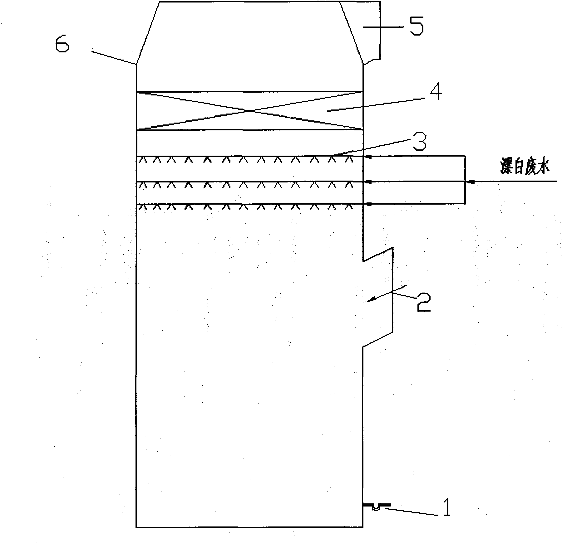
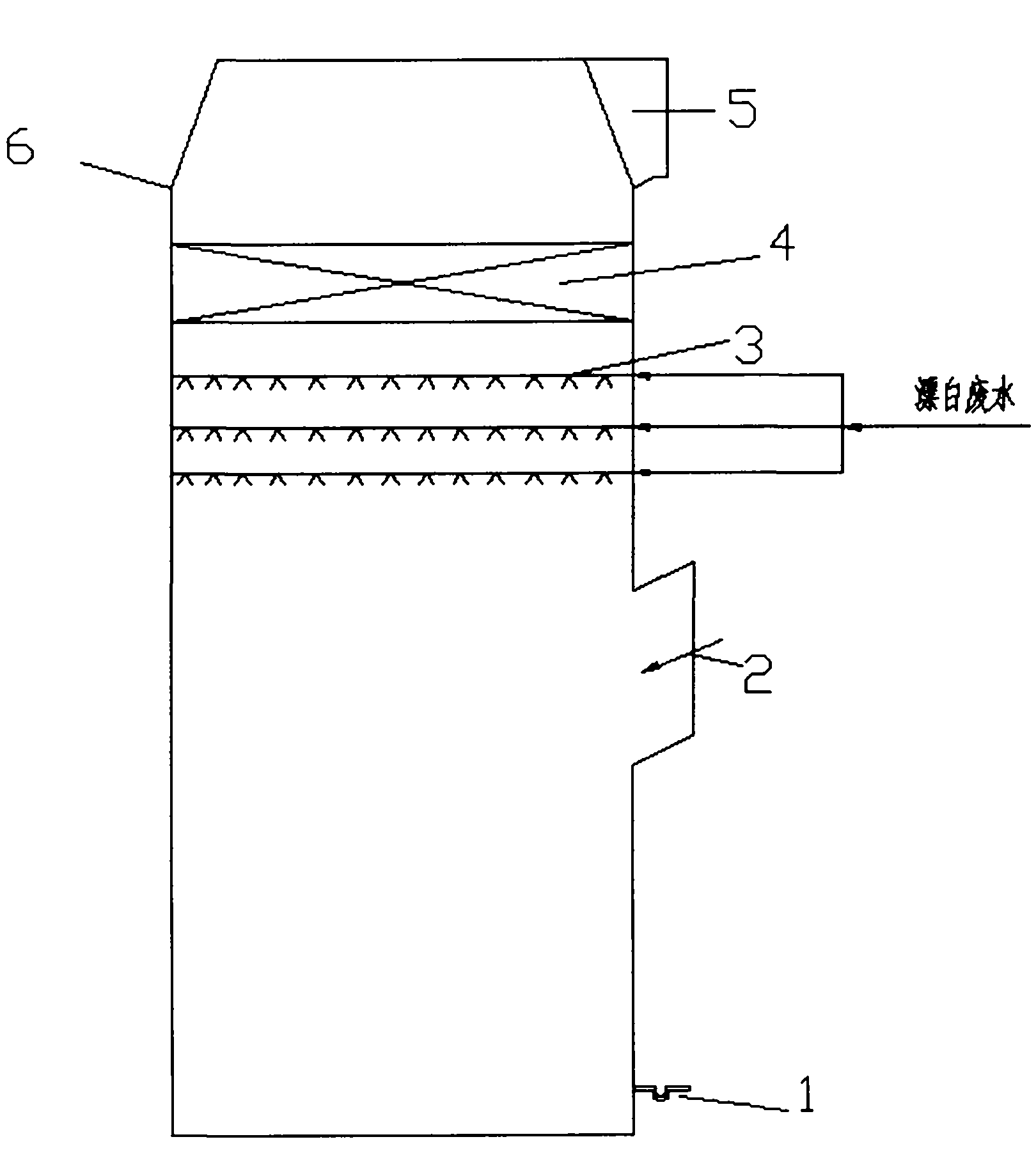
[0034] like figure 1 Absorption tower for flue gas denitrification with bleaching wastewater as shown

[0035] An absorption tower for flue gas denitrification by bleaching wastewater, comprising an absorption tower 6, and the desulfurization tower 6 includes a flue gas inlet 2, a flue gas outlet 5, an overflow port 1, a slurry spray area 3, and a demister area 4;

[0036] The flue gas outlet 5 is opened on the top of the absorption tower 6, and an overflow port 1 is opened on the side of the bottom of the absorption tower;

[0037] The inclination angle between the flue gas inlet 2 and the horizontal plane is 10-20°;

[0038] The overflow port is a U-shaped liquid outlet channel;

[0039] The slurry spraying area 3 is provided with 3 layers of staggered bleaching wastewater spraying layers; the spraying layer is provided with a spray pipe and a number of nozzles connected thereto;

[0040] The upper demister section 4 of the absorption tower 6 can remove liquid droplets i...

Embodiment 2

[0042] The bleaching wastewater flue gas denitrification device of the present invention is used for denitrification.

[0043] The flue gas discharged from the boiler, in which the NO concentration is 1339mg / m 3 , after the dust is removed by the electrostatic precipitator, the flue gas flow rate is selected to be 6785m through the booster fan 3 / h is sent into the absorption tower 6 through the flue gas inlet 2 of the absorption tower 6, and passes through the spray area 5 arranged staggeredly above the absorption tower 6, and the bleaching wastewater flows at a flow rate of 67.85m 3 / h is continuously transported to the spray area 3, sprayed out through the nozzle, and contacts with the flue gas countercurrently, thereby completing the denitrification. The reacted absorption liquid falls into the bottom of the absorption tower 6, and then is discharged through the overflow port 1 and sent to the waste water treatment device. At the flue gas outlet 5, the testo 350XL flue g...


PUM


Abstract

The invention relates to an absorption tower for denitrating flue gas by using bleaching effluent and a denitrating method thereof. The absorption tower comprises a tower body, wherein the top of the tower is provided with a flue gas outlet, the bottom is provided with an overflow vent, and the tower body is sequentially provided with a flue gas inlet, a slurry spraying area and a demister area from bottom to top. In the method for denitrating the flue gas by using the bleaching effluent, NOx in the flue gas is removed by using the bleaching effluent, therefore, the flue gas can be discharged after reaching standards, acidic materials which are added when the bleaching effluent is discharged can be saved, and the chemical oxygen demand (COD) of the bleaching effluent after denitration can be greatly reduced, which is beneficial to further treating the bleaching effluent at a sewage treatment station. By adopting the method, waste water and exhaust gas are comprehensively treated, and the cost for treating the waste water and the exhaust gas is greatly reduced.

Description

technical field [0001] The invention relates to the technical field of waste water and waste gas treatment equipment, in particular to an absorption tower for denitrating flue gas with bleaching waste water and a denitrification method thereof. Background technique [0002] In recent years, my country's economy has developed rapidly, and power demand and supply have continued to grow. my country's total installed capacity of power generation and thermal power has also been on the rise; for a long time to come, my country will maintain the basic pattern of using coal as the main energy source. The combustion of coal will produce a large number of harmful pollutants: nitrogen oxides (NOx), heavy metal mercury, sulfur dioxide and soot. As a large power consumer with high energy consumption, the papermaking industry often has its own power plant. The bleaching wastewater generated in the papermaking process and the NOx pollution generated in the power generation process have br...

Claims


Application Information

Patent Timeline
Patent Type & Authority Applications(China)
IPC IPC(8): B01D53/56B01D53/78
Inventor 郭瑞堂潘卫国冷雪峰张晓波徐宏建
Owner SHANGHAI UNIVERSITY OF ELECTRIC POWER
Why Eureka
Try Eureka