Method and device for cutting metal-moulded honeycomb thin wave plate

A metal forming and cutting device technology, applied in shearing devices, metal processing equipment, shearing machine equipment, etc., can solve the problems of oblique cutting of the angle of the uncut end face, not suitable for cutting the corrugated plate, unable to cut the corrugated plate, etc. Low equipment requirements, uniform force and small cutting force

Inactive Publication Date: 2010-08-18
JIANGSU RUISHENG WATER TREATMENT
View PDF10 Cites 5 Cited by
  • Summary
  • Abstract
  • Description
  • Claims
  • Application Information

AI Technical Summary

Problems solved by technology

[0005] Arc cutting, such as plasma cutting, not only cannot cut corrugated plates, but also has a larger amount of thermal deformation and a large investment in equipment. The above-mentioned shortcomings of cutting still exist, and it is actually impossible to use
[0006] Chinese patent CN1333103 ultra-thin metal plate laser cutting processing device can only be used for flat plate cutting, not for corrugated plate cutting
[0007] Chinese patents CN1986129, CN201052559 hydraulic roll-cutting type metal plate shears, and Chinese patent CN2187084 program-controlled plate strip hydraulic flying shears can only cut metal flat plates, and are not suitable for corrugated plate cutting. Controlled by one oil cylinder, in order to ensure simultaneous cutting on both sides, the control is difficult and complicated
[0008] Therefore, in the prior art, there is no method and device for cutting wide and multiple waves, and the superimposed surface is required to be flat, especially the wave height is relatively high, and it is V-shaped or vertical straight (trapezoidal or rectangular) wave plate cutting method and device, and there is no cutting end surface that is angle cut off

Method used


Image

  • Method and device for cutting metal-moulded honeycomb thin wave plate
  • Method and device for cutting metal-moulded honeycomb thin wave plate
  • Method and device for cutting metal-moulded honeycomb thin wave plate

Examples


Embodiment

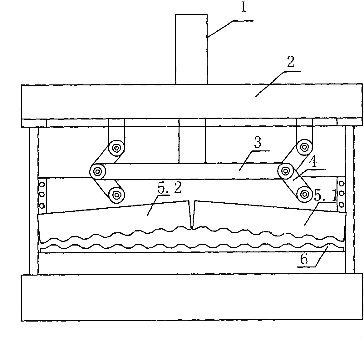
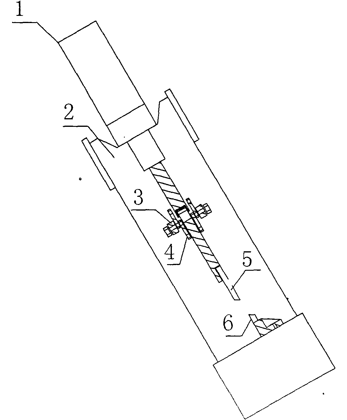
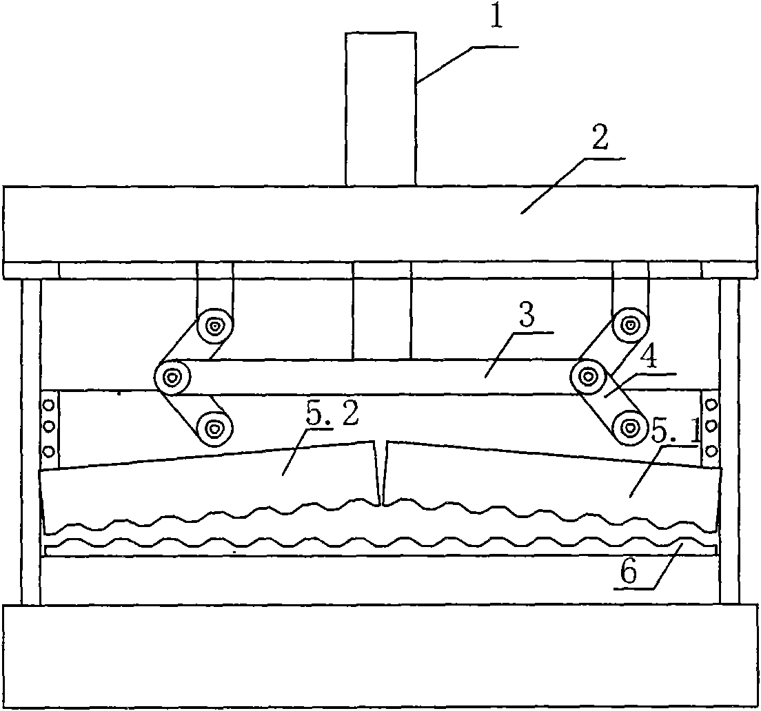
[0020] Embodiment: referring to the drawings, the punching and cutting device of the present invention that cuts both sides to the middle at the same time in a shearing manner includes a rectangular frame 2 that fixes the upper and lower blade rows and the power. The upper beam of the frame is provided with a driving shear Hydraulic cylinder 1, the upper part of the frame has an upper knife rack that moves up and down to form a punching shear, and is limited by the left and right vertical rods on both sides of the frame. The upper knife rack is driven by the cylinder for punching and shearing movement, and the bottom is dislocated and fixed with the lower knife Row 6. The upper knife row has two left and right knife rows 5.1 and 5.2, which are fixed on the upper knife rack with a bottom angle of 10 degrees facing each other in an "eight" shape. The upper and lower knife rows have the same shape and complement each other as the cut honeycomb. Between the upper knife rack and the...


PUM


Abstract

The invention relates to a method and a device for cutting a metal-moulded honeycomb thin wave plate, which are characterized in that: the cutting is performed from two sides to the middle part of the wave plate in a shearing way to make a shearing face at an oblique angle of 60+/-10 degrees. The method and the device simply and obliquely cut the moulded honeycomb thin wave plate accurately at one time without additionally processing the oblique angle; at the same time, a cutting opening is flat and straight, has no burr edge and does not need to be deburred; and the cutting force in opposite direction is uniform and does not cause wave deformation, so secondary reshaping and processing are not needed. An upper cutter cuts at a high speed and with a high cutting efficiency while moving downwards and is used together with a wave plate continuously moulding machine; and equipment is simple and can obliquely cut at any oblique angle. A balance device arranged on the upper cutter can ensure that shearing on two sides is synchronous and that the shearing does not deform substantially. The cutting method of cutting from two sides to the middle part in the shearing way is weak in cutting force, simple in used equipment, low in requirement on the equipment and low in cost.

Description

Technical field [0001] The invention relates to a metal plate cutting device, in particular to a method and a device for cutting a wave plate of a metal formed honeycomb inclined tube with a higher wave height. Background technique [0002] Metal plate cutting includes punching, cutting machine cutting, arc cutting and other methods. Most of these cuttings are used for flat cutting. The formed stainless steel honeycomb oblique tube wave plate for water treatment is a multiple-phase trapezoidal or rectangular wave structure. The cut surface is not the same plane, and the width is about 1 meter. The wave height is relatively high, such as 20mm. The thickness of the wave plate is less than 0.5mm. After the continuous forming, the cutting method is not deformed, smooth and without burrs, which is very difficult, and the existing cutting methods are not applicable. [0003] The metal plate punching and cutting method not only requires high equipment requirements and large investment, b...

Claims


Application Information

Patent Timeline
Patent Type & Authority Applications(China)
IPC IPC(8): B23D15/06
Inventor 季亦强朱行平刘雪锋王涛周丽君陈浩森
Owner JIANGSU RUISHENG WATER TREATMENT
Why Eureka
Try Eureka