System and method for using sintering waste heat to generate electricity

A waste heat power generation and sintering machine technology, which is applied in waste heat treatment, machinery/engine, lighting and heating equipment, etc., can solve the problems of unstable operation of waste heat power generation, low sensible heat utilization rate and high operating cost, and reduce equipment investment. , The effect of reducing equipment investment and operating costs, and reducing operating costs

Inactive Publication Date: 2010-08-18
湖南永清环境科技产业集团有限公司
View PDF4 Cites 53 Cited by
  • Summary
  • Abstract
  • Description
  • Claims
  • Application Information

AI Technical Summary

Problems solved by technology

[0005] In view of the defects that the existing sintering waste heat power generation system needs to be equipped with an induction fan to extract the flue gas, the operating cost is high, the failure rate is high, and the waste heat power generation in the waste heat power generation method is unstable and the utilization rate of heat is not high, the purpose of the present invention is to provide A sintering waste heat power generation system and method, without affecting the normal production of the sintering process and ensuring the sintering quality, the sintering waste heat power generation system fully utilizes the flue gas of the non-desulfurization pipe at the tail of the sintering machine and the waste heat of the exhaust gas of the cooler, and adopts sintering There is no induction fan for the flue gas at the tail of the waste heat boiler, and the method of leading out the hot exhaust gas in the first and second stages of the annular cooler and the method of partial recycling can make full use of the flue gas of the sintering machine and the waste heat of the exhaust gas of the annular cooler, reducing equipment investment and reducing Reduce operating costs and increase the power generation of sintering waste heat power generation system

Method used


Image

  • System and method for using sintering waste heat to generate electricity
  • System and method for using sintering waste heat to generate electricity

Examples


Embodiment Construction

[0040] The present invention will be further described below in conjunction with accompanying drawing.

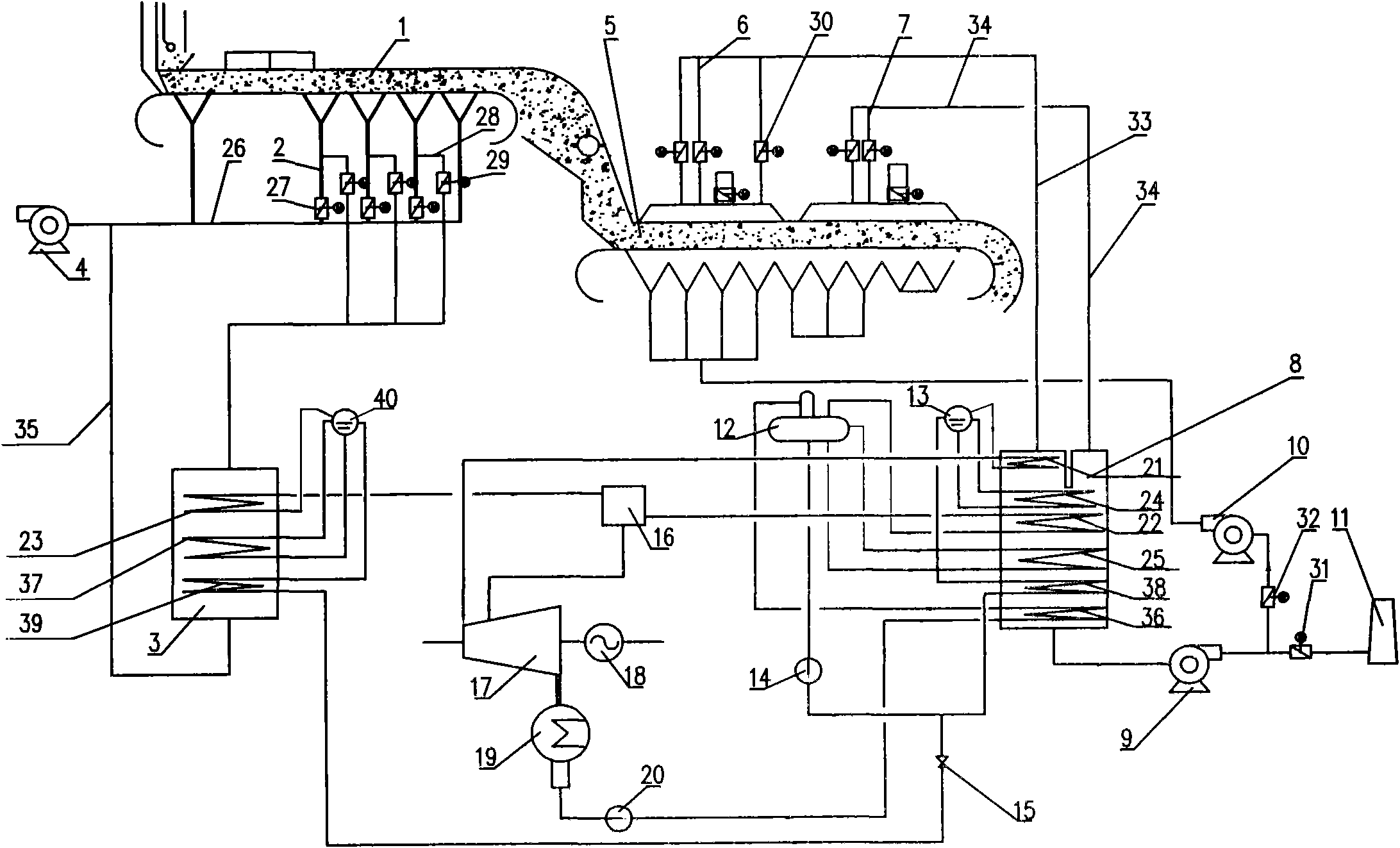
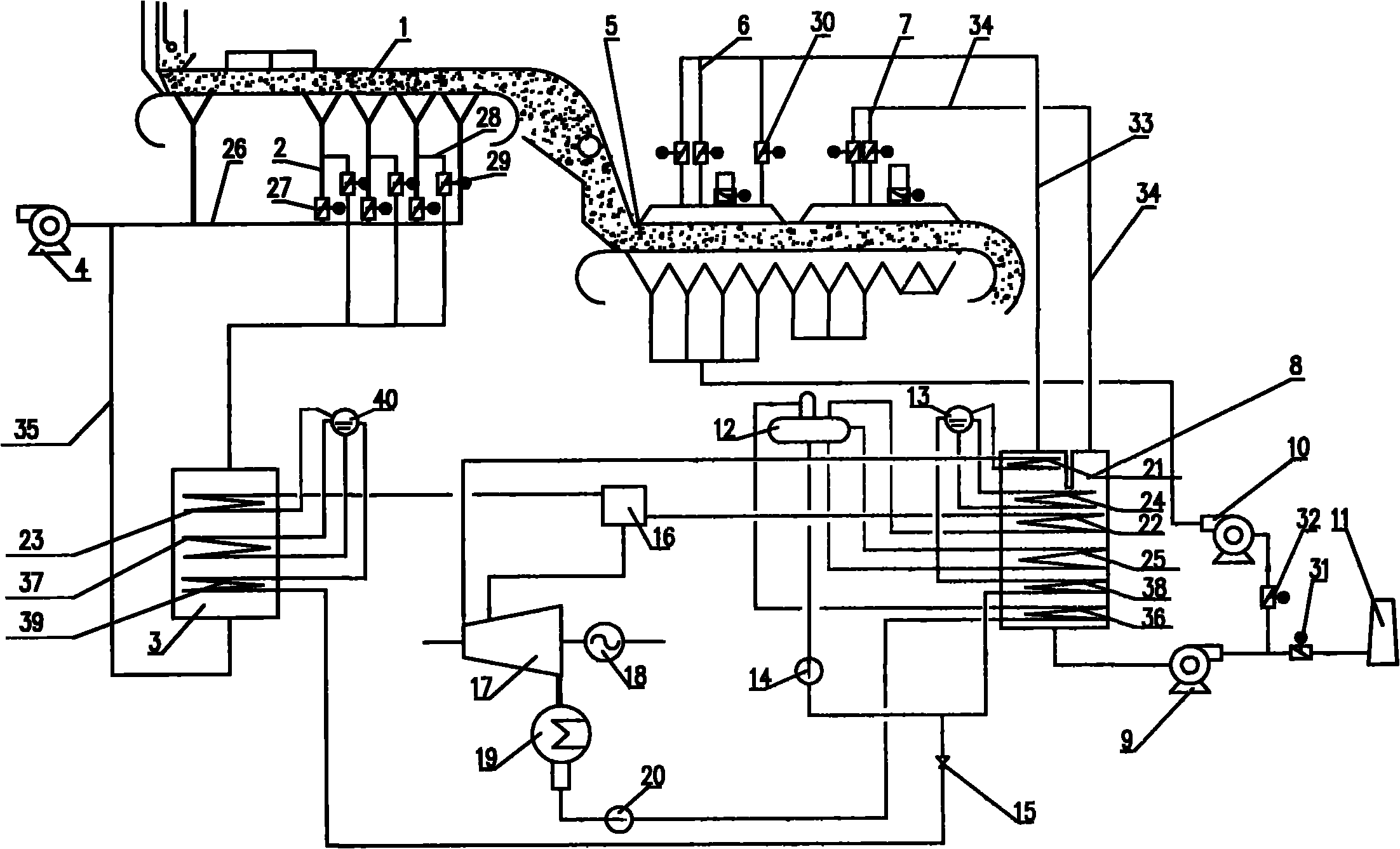
[0041] A sintering waste heat power generation system, such as figure 1 As shown, including sintering machine hot flue gas system, hot waste gas waste heat utilization system and sintering waste heat power generation thermal system;

[0042] The hot flue gas system of the sintering machine is as follows: a hot flue gas outlet pipe 2 is provided in each of the bellows at the bottom of the sintering machine 1, and the other end of the hot flue gas outlet pipe 2 communicates with the hot flue gas manifold 26 at the tail. Each hot flue gas outlet pipe 2 is provided with a hot flue gas outlet pipe valve 27 at one end close to the hot flue gas manifold 26 at the tail, and a main exhaust fan 4 is arranged at one end of the hot flue gas manifold 26 at the tail, counting down from the tail of the sintering machine Starting from the second hot flue gas outlet pipe 2, hot flue gas br...


PUM


Abstract

The invention discloses a system and a method for using sintering waste heat to generate electricity and belongs to the technical field of sintering waste heat electricity generation of the steel works. The system comprises a sintering machine, a hot gas outlet pipe, a gas waste heat boiler, a main exhaust fan, a ring cooling machine, a first and second stage heat waste gas collecting pipe, a waste gas heat boiler, a draught fan, a circulating fan, a chimney, a low pressure steam drum, a middle pressure steam drum, a feed pump, a pressure reducing valve, a collecting header, a steam turbine, a generator, a condenser and a condensate pump. The invention realizes utilizing the waste heat of the non-desulfurization flue header of the sintering machine without arranging an inducing fan by reasonably designing the hot gas connecting mode of the air box at the tail part of the sintering machine and the gas resistance of the waste gas heat boiler. First and second stage sealing covers of the ring cooling machine are uniformly provided with a plurality of waste gas branch pipes so as to realize uniform distribution of the waste gas pressure in the sealing covers and reduce air leakage. Part of waste gas is adopted to circulate to improve the temperature of the waste gas. Compared with the existing system for using sintering waste heat to generate electricity, the system of the invention sufficiently uses the waste heat of the sintering system, improves the waste heat generated energy and reduces the operation cost.

Description

technical field [0001] The invention belongs to the technical field of sintering waste heat power generation in iron and steel plants, and in particular relates to a sintering waste heat power generation system and method, which uses the waste heat of sintering machine hot flue gas and cooling machine hot waste gas to generate electricity. Background technique [0002] In the process of iron and steel production, the energy consumption of the sintering process accounts for about 10% of the total energy consumption, ranking second only to the iron-making process. In the total energy consumption of the sintering process, nearly 50% of the heat energy is discharged into the atmosphere in the form of sensible heat from the flue gas of the sintering machine and the exhaust gas of the cooling machine. Power generation by sintering waste heat is an important measure for steel plants to achieve energy conservation and emission reduction. [0003] The sulfur content of the flue gas i...

Claims


Application Information

Patent Timeline
Patent Type & Authority Applications(China)
IPC IPC(8): F01K11/00F27D17/00
CPCY02P10/25
Inventor 刘志永易新建王旭伟李秀莉杨朝晖
Owner 湖南永清环境科技产业集团有限公司
Why Eureka
Try Eureka