Transparent flexible ultraviolet detector and preparation method thereof

An ultraviolet detector and transparent technology, applied in the field of photodetectors, can solve the problems of complex process, high preparation cost, inflexibility, etc., and achieve the effect of abundant resources and simple process

Inactive Publication Date: 2010-08-18
HENAN UNIVERSITY
View PDF4 Cites 21 Cited by
  • Summary
  • Abstract
  • Description
  • Claims
  • Application Information

AI Technical Summary

Problems solved by technology

At present, most ZnO-based ultraviolet detectors use silicon wafers, quartz or sapphire as substrates, and use metal materials as interdigitated

Method used


Image

  • Transparent flexible ultraviolet detector and preparation method thereof
  • Transparent flexible ultraviolet detector and preparation method thereof
  • Transparent flexible ultraviolet detector and preparation method thereof

Examples


Embodiment 1

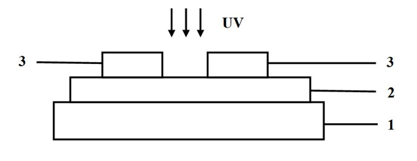
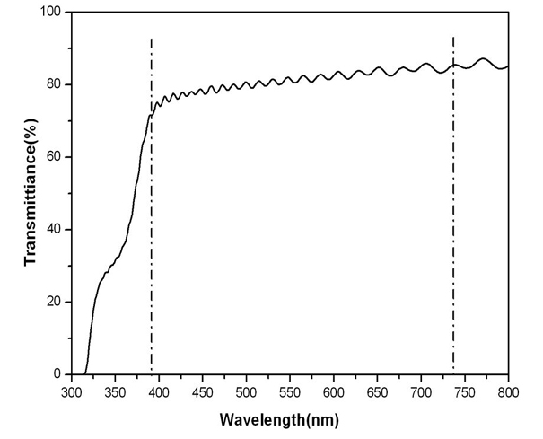
[0022] The ultraviolet detector structure of the present embodiment is as figure 1 As shown, a transparent plastic substrate 1 is included, a 100nm thick ZnO film 2 is deposited on the surface of the transparent plastic substrate 1, a 100nm thick ITO transparent interdigital electrode 3 is arranged on the surface of the ZnO thin film 2, and between adjacent interdigital electrodes The interdigital spacing between them is 600 μm. The material used for the transparent plastic substrate in this embodiment is polyethylene terephthalate (PET) film. The light transmittance of the ultraviolet detector obtained by testing is as follows: figure 2 As shown, the transmittance of the ultraviolet detector in the visible light band reaches 80%, realizing the transparency of the ultraviolet detector.

[0023] The preparation method of the ultraviolet detector of the present embodiment is as follows:

[0024] 1) Clean the polyethylene terephthalate (PET) transparent flexible substrate, dr...

Embodiment 2

[0030] The ultraviolet detector of this embodiment is basically the same as that of Embodiment 1, except that the thickness of the ZnO thin film is 50 nm, the thickness of the ITO interdigitated electrode is 100 nm, and the interdigital distance is 200 μm.

[0031] The preparation method of the ultraviolet detector of this embodiment is the same as that of Embodiment 1, the difference is that the parameters of the pulsed laser deposition are: high-purity oxygen ambient pressure is 50Pa, the pulsed laser energy is 300mJ, the pulsed laser frequency is 3Hz, and the growth time is 30min; The magnetron sputtering parameters are as follows: the ambient pressure of high-purity argon is 5Pa, the sputtering power is 200W, and the sputtering time is 30min.

Embodiment 3

[0033] The ultraviolet detector of this embodiment is basically the same as that of Embodiment 1, except that the thickness of the ZnO thin film is 200 nm, the thickness of the ITO interdigitated electrode is 300 nm, and the interdigital distance is 1000 μm.

[0034] The preparation method of the ultraviolet detector of this embodiment is the same as that of Embodiment 1, the difference is that the parameters of the pulsed laser deposition are: high-purity oxygen ambient pressure is 50Pa, the pulsed laser energy is 300mJ, the pulsed laser frequency is 3Hz, and the growth time is 30min; The magnetron sputtering parameters are as follows: the ambient pressure of high-purity argon is 20Pa, the sputtering power is 80W, and the sputtering time is 200min.


PUM

PropertyMeasurementUnit
Thicknessaaaaaaaaaa
Thicknessaaaaaaaaaa
Interdigital spacingaaaaaaaaaa

Abstract

The invention discloses a transparent flexible ultraviolet detector and simultaneously discloses a preparation thereof. The transparent flexible ultraviolet detector comprises a transparent plastic substrate, a ZnO-based active layer is deposited on the surface of the transparent plastic substrate, and transparent interdigital electrodes are arranged on the surface of the ZnO-based active layer; and the transparent plastic substrate is a polyethylene terephthalate film, a polyethylene naphthalate film, a polysulfone resin film or an organic glass film. The invention realizes the transparency and flexibility of the ultraviolet detector and broadens the application scope of the ultraviolet detector. In addition, the whole preparation process of the ultraviolet detector is completed at the room temperature, the process flow is simple, the ZnO material resources are rich and non-toxic, and the preparation process is suitable for industrial production.

Description

technical field [0001] The invention relates to an ultraviolet detector and a preparation method of the ultraviolet detector, belonging to the technical field of photoelectric detectors. Background technique [0002] Ultraviolet light refers to electromagnetic waves with a wavelength between 200nm and 400nm, which widely exist in nature and people's lives. Ultraviolet detection technology is another new type of detection technology developed after infrared detection and laser detection. It is widely used in environmental monitoring, astronomy, national defense, military and sky communication. The ultraviolet detection devices currently used are still mainly vacuum photomultiplier tubes and ultraviolet-enhanced silicon photodiodes. The former is large in size and high in operating voltage; Application poses difficulties. In addition, with the aggravation of the destruction of the ozone layer in the atmosphere, the ultraviolet light irradiated to the earth's surface is getti...

Claims


Application Information

Patent Timeline
IPC IPC(8): H01L31/09H01L31/02H01L31/18
CPCY02P70/50
Inventor 张新安张伟风丁玲红吴永辉王昊午
Owner HENAN UNIVERSITY
Why Eureka
Try Eureka