
Rapid three-dimensional photoacoustic imaging system based on ultrasonic plane array detector and method thereof

An ultrasonic detector and photoacoustic imaging technology, which is applied in the generation of ultrasonic/sonic/infrasonic waves, and the use of sound waves/ultrasonic/infrasonic waves to analyze solids, etc., can solve the problem of affecting the reliability and authenticity of reconstructed image imaging results, which is difficult to achieve Problems such as fast and real-time imaging, experimental equipment and imaging algorithms are complex, to achieve the effect of being widely used and overcoming slow imaging speed and high contrast

Active Publication Date: 2010-08-25
SOUTH CHINA NORMAL UNIVERSITY
View PDF3 Cites 27 Cited by
  • Summary
  • Abstract
  • Description
  • Claims
  • Application Information

AI Technical Summary

Problems solved by technology

Mobile detectors generally adopt the method of tomographic 360°rotational scanning or plane point scanning, but either way has the disadvantages of long data acquisition time, complex experimental equipment and imaging algorithms, etc.
Moreover, during the long-term mechanical scanning and data acquisition process, inevitable factors such as mechanical vibration, electronic equipment stability, and working point drift will bring random errors to the imaging results, thereby affecting the quality of the reconstructed image and the reliability and reliability of the imaging results. authenticity
Recently, two-dimensional detectors have the capability of lateral tomography at different depths, but they need to rely on hardware signal delay circuits to achieve selective imaging of signals at different acquisition depths. In fact, it is difficult to achieve fast and real-time imaging.

Method used


Image

  • Rapid three-dimensional photoacoustic imaging system based on ultrasonic plane array detector and method thereof
  • Rapid three-dimensional photoacoustic imaging system based on ultrasonic plane array detector and method thereof
  • Rapid three-dimensional photoacoustic imaging system based on ultrasonic plane array detector and method thereof

Examples


Embodiment 1

[0034] Embodiment 1 The device and image algorithm of the present invention

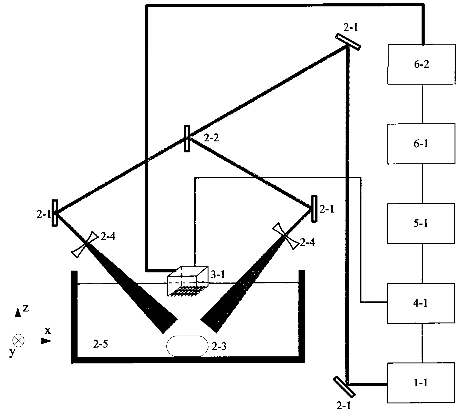
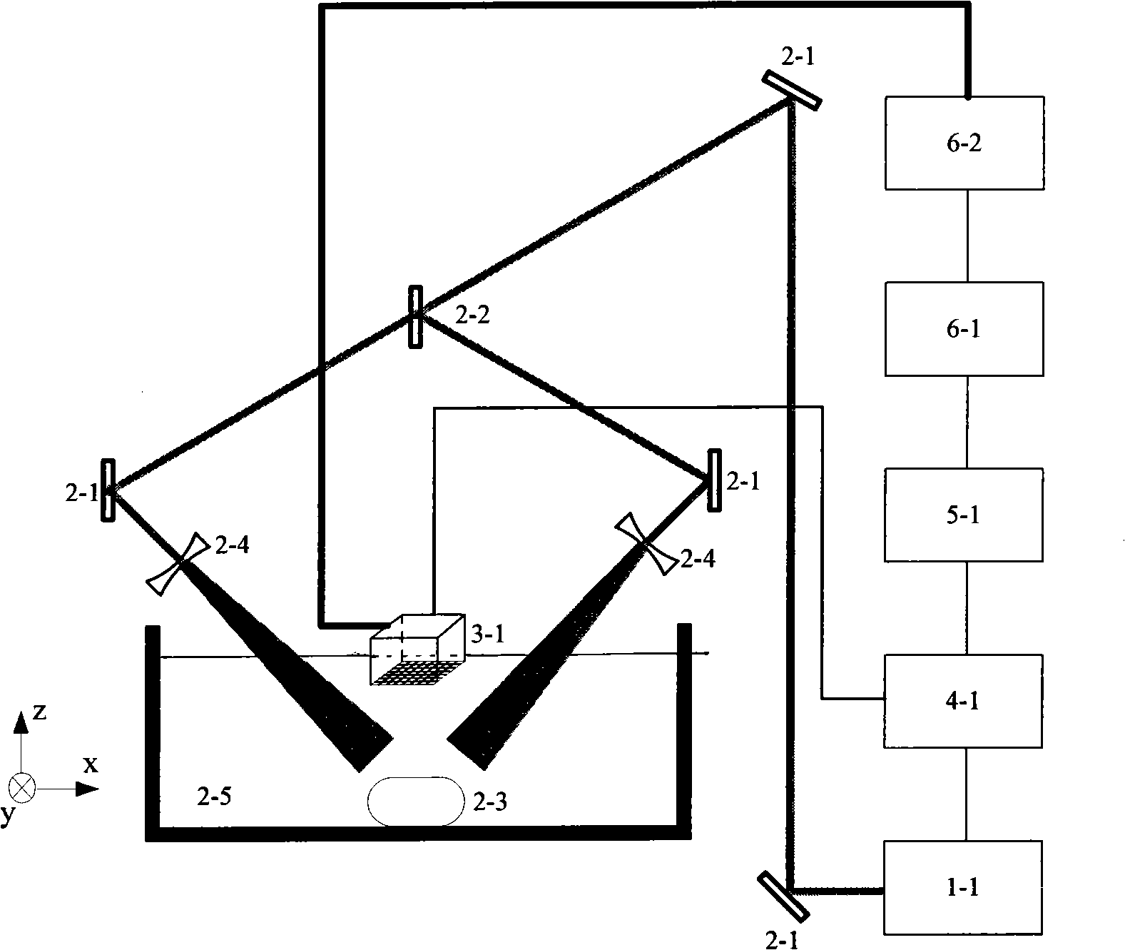
[0035] Fig. 1 is the schematic diagram of the principle structure of the whole set of imaging device of the present invention, and this device is made up of four major parts, is respectively photoacoustic signal generation device, photoacoustic signal acquisition and transmission equipment, control probe translation equipment, computer component; connect. The laser 1-1 of the photoacoustic signal generating device is an Nd:YAG pumped OPO laser (Vibrant 532 I, Opotek, Carlsbad, Calif.), the output laser wavelength is 690-960nm, the pulse width is 10ns, and the repetition frequency is 10Hz . The OPO emits a pulsed laser beam, which passes through the mirror 2-1 twice and is divided into a beam of reflected light and a beam of transmitted light by the beam splitter 2-2 at an incident angle of 45°; two beams of equal energy are respectively placed symmetrically and vertically After the reflection mirro...

Embodiment 2

[0038] Embodiment 2 The device and method of Embodiment 1 are used to realize the photoacoustic imaging of the transverse section of the simulated sample.

[0039] First, mix 13% gelatin, 12.5% ​​milk, and 74.5% water to make a square model, and then select two hairs with a length of about 6mm and a size of 100um and bury them in the model with a depth of 5mm. The root hair is placed horizontally and parallel to the plane detector 3-1, with a distance of about 4mm. At the same time, the position of the detector 3-1 is fixed above the sample 2-3 and the distance between the detector 3-1 and the hair plane is adjusted to 4mm. . In the experiment, the operating frequency of OPO laser 1-1 is 15Hz, the pulse width is 10ns, and the wavelength is 532nm. The pulsed laser beam passes through the optical path of the device and evenly covers the two hairs. The photoacoustic signal generated by the excitation is received by the planar detector 3-1, and after the pre-filtering and prevent...

Embodiment 3

[0040] Embodiment 3 The device and method of Embodiment 1 are used to realize the photoacoustic imaging of the longitudinal section of the simulated sample.

[0041] Similar to Example 2, two hair strands of the same size and size as in Example 2 are also placed in a model with the same composition, and the two hair strands are placed parallel to each other in a certain plane perpendicular to the detector 3-1 , the same distance is 4mm. The distances from the detector 3-1 to the two hairs are 28mm and 32mm respectively. The experimental laser 1-1 works at a frequency of 15 Hz, a pulse width of 10 ns, and a wavelength of 532 nm. After splitting, the two laser beams uniformly irradiate the sample 2-3 at different depths, and the generated photoacoustic signal is received by the detector 3-1, preprocessed by the parallel acquisition system 4-1, and then transmitted to the computer 5-1 Complete image reconstruction. Figure 5(a) and (b) show the longitudinal reconstructed tomogr...


PUM

PropertyMeasurementUnit
Wavelengthaaaaaaaaaa

Abstract

The invention discloses a rapid three-dimensional photoacoustic imaging system based on an ultrasonic plane array detector which has the advantages of simple operation, low manufacturing cost and convenient detection and an imaging method thereof. The rapid three-dimensional photoacoustic imaging method based on the ultrasonic plane array detector mainly comprises the following steps: adopting a laser pulse to excite ultrasonic signals which can produce a light induced thermal elastic effect, collecting photoacoustic signals in parallel simultaneously with a plane array detector and multiple array elements, processing the signals in a three-dimensional phase-controlled algorithm, and reconstructing an optical absorption and distribution image for a sample to be detected. The three-dimensional photoacoustic imaging device comprises a photoacoustic excitation source device, a photoacoustic signal receiving and collecting device and a computer component. The invention overcomes the defects of the traditional technology such as low imaging speed, poor stability due to long-term system operation, complex device and the like, simultaneously combines the advantages of pure acoustics and pure optical imaging, and can provide images reflecting optical absorption and distribution of tissues. The device of the invention has the advantages of simple structure and easy promotion.

Description

technical field [0001] The invention relates to a non-destructive fast imaging technology, in particular to a fast three-dimensional photoacoustic imaging system and method based on an area array ultrasonic detector. Background technique [0002] As a novel non-destructive material structure detection technology, photoacoustic imaging has been greatly developed in the past ten years. Photoacoustic imaging is based on the principle of photoacoustic effect. When it is a substance, the part with light energy absorption characteristics in the substance produces periodic instantaneous temperature changes, so that the light-absorbing medium here and the surrounding substances produce periodic stress or pressure changes due to thermal expansion, and finally by this effect The ultrasonic signal is generated by changing the force, which is the photoacoustic signal. The photoacoustic effect is actually a conversion process of light energy to sound energy. The photoacoustic signal is...

Claims


Application Information

Patent Timeline
IPC IPC(8): G01N29/34G01N29/04
Inventor 杨思华邢达周求真
Owner SOUTH CHINA NORMAL UNIVERSITY
Learn More