

Solar oil heat conducting and supplying device
A heating device and solar energy technology, which is applied in the direction of solar thermal devices, solar thermal energy, solar thermal power generation, etc., can solve the problems of energy waste, easy loss of heat energy, singleness, etc., and achieve the effect of energy saving and heat energy
- Summary
- Abstract
- Description
- Claims
- Application Information
AI Technical Summary
Problems solved by technology
Method used
Image

Examples
Embodiment 1
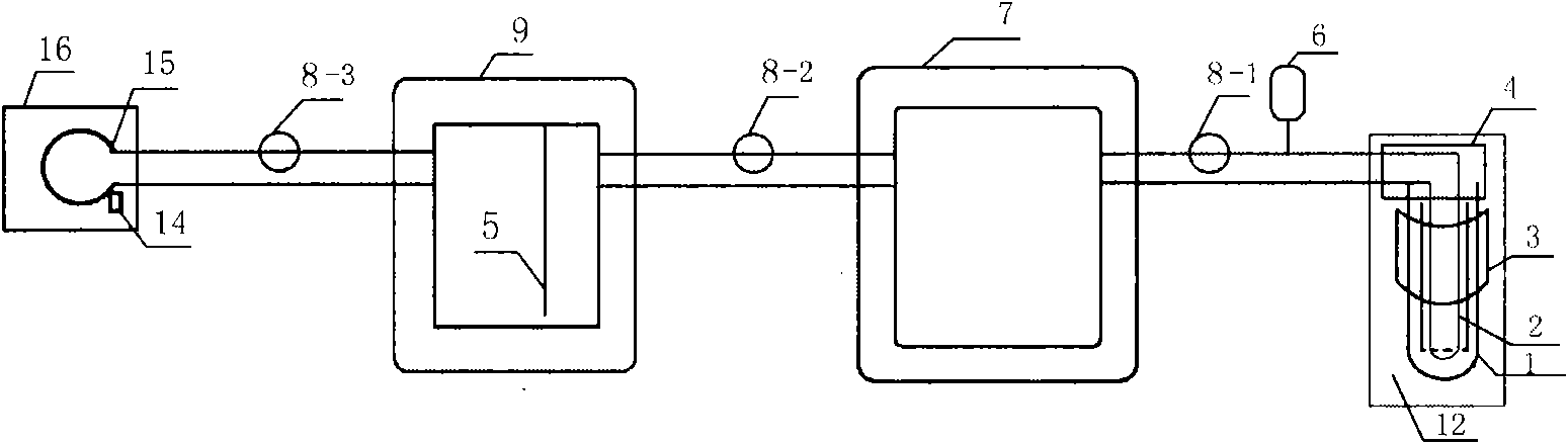
[0067] Solar oil heat conduction heating device: such as figure 1 As shown, the solar tube 12 of the present invention is composed of a solar vacuum tube 1 , a U-shaped metal blade tube 2 , a reflector 3 and a connection box 4 . The U-shaped metal blade tube 2 is a U-shaped metal tube with heat-absorbing blades on it. The U-shaped metal blade tube 2 is inserted into the solar vacuum tube 1. The blades of the U-shaped metal blade tube 2 are attached to the inner wall of the solar vacuum tube 1. The solar vacuum tube 1 Reflector 3 is equipped with below, and two metal pipes and insulation material are arranged in connection box 4, and the two ends of U-shaped metal blade pipe 2 are connected with two metal pipes in connection box 4 respectively. The solar vacuum tube 1 transmits solar energy to the U-shaped metal blade tube 2. The U-shaped metal tube 2 is used to hold heat transfer oil. The connection box 4 can connect multiple sets of solar tubes. The heat transfer oil in the s...
Embodiment 2
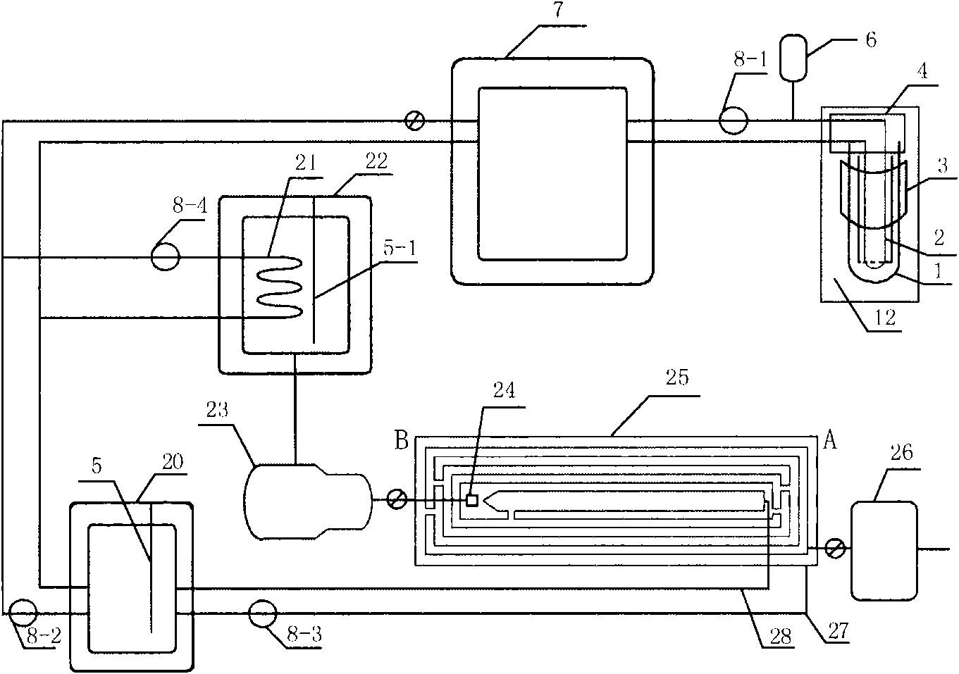
[0070] Solar oil heat conduction steam generator: when the sun is sufficient, such as figure 2 As shown, the solar tube 12 is connected with the oil inlet and outlet of the energy storage tank 7 through two pipelines in the connection box 4. The energy storage tank 7 has a thermal insulation layer, and the inside of the tank body is empty for holding oil conduction heat. One of the pipelines connecting the energy storage tank 7 and the solar tube 12 is equipped with a circulation pump 8-1 and is connected to the expansion tank 6 . The outlet and oil inlet of the energy storage tank 7 are respectively connected with the inlet and outlet of the hot water exchanger 22 and the inlet and outlet of the oil constant temperature tank 20 through pipelines. The hot water exchanger 22 has an insulation layer and a metal coil 21, For heating water, the inside of the tank is empty and used to hold water. One of the pipelines connected to the energy storage tank 7 is equipped with a circul...
Embodiment 3
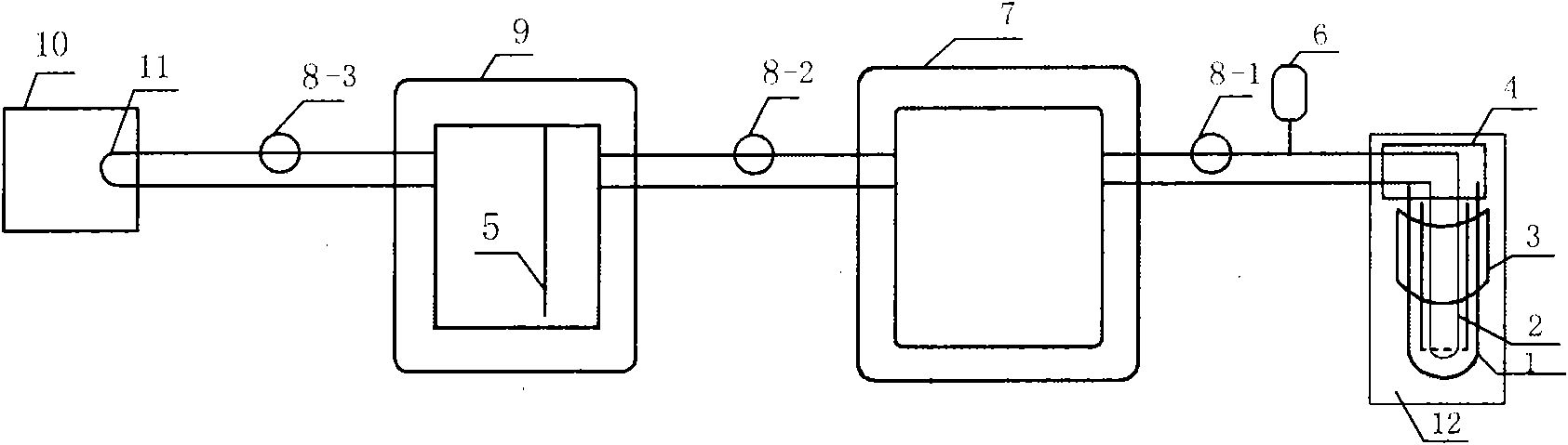
[0074] Solar oil heat conduction stove: when the sun is sufficient, such as figure 1 As shown, the solar tube is connected with the oil inlet and outlet of the energy storage tank 7 through two pipelines in the connection box 4, and the energy storage tank 7 has a thermal insulation layer, and is used for containing oil conduction heat in the tank. One of the pipelines connecting the energy storage tank 7 and the solar tube is equipped with a circulating pump 8-1 and is connected to the expansion tank 6. The outlet and oil inlet of the energy storage tank 7 are connected with the oil inlet and outlet of the oil constant temperature tank 9 through pipelines. One of the pipelines connected to the energy storage tank 7 is equipped with a circulation pump 8-2. The outlet and oil inlet of the oil constant temperature tank 9 are connected with the inlet and outlet of the metal coil pipe 15 in the cooking range 16 by pipelines.
[0075] Heat conduction oil is injected into solar tu...
PUM
 Abstract
Description
Claims
Application Information