Novel drying oven and drying method thereof

A drying method and drying oven technology, which is applied in the direction of drying solid materials, drying chambers/containers, local agitation dryers, etc., can solve the problems of water vapor mass transfer and heat transfer limitations, changes in the properties of materials to be dried, and incomplete drying of materials, etc. , to achieve the effects of not being easy to stay and condense, improving flow and distribution, and reducing the temperature of the drying process

Active Publication Date: 2010-09-01
康纳新型材料(杭州)有限公司
View PDF6 Cites 12 Cited by
  • Summary
  • Abstract
  • Description
  • Claims
  • Application Information

AI Technical Summary

Problems solved by technology

Commonly used vacuum ovens have some obvious shortcomings. For example, traditional laboratory vacuum drying ovens use indirect heating on the side wall, and the heat transfer is slow and the efficiency is very low under high vacuum conditions.
Or although the heating plate of a large industrial oven can be directly heated, the heating plate is a whole piece (such as Image 6 As shown), the water vapor mass transfer and heat transfer in the oven are very limited
Water vapor is easy to stay or condense on the upper and lower plates or the dead corner of the inner wall of the oven, and it is difficult to remove
There are similar problems in the drying treatment of non-aqueous organic gases, such as ethanol, which leads to incomplete drying of substances
In order to achieve a good drying effect, it is necessary to increase the drying temperature or greatly extend the drying time, but this will cause changes in the properties of the material to be dried, performance degradation or decomposition of nutrients, and greatly increase energy consumption and reduce work efficiency. This is especially obvious in the fields of medicine, food processing, biological agents, catalysts, pesticides, flavors and fragrances, dyes, pigments, health products, daily chemicals, etc.

Method used


Image

  • Novel drying oven and drying method thereof
  • Novel drying oven and drying method thereof
  • Novel drying oven and drying method thereof

Examples


Embodiment 1

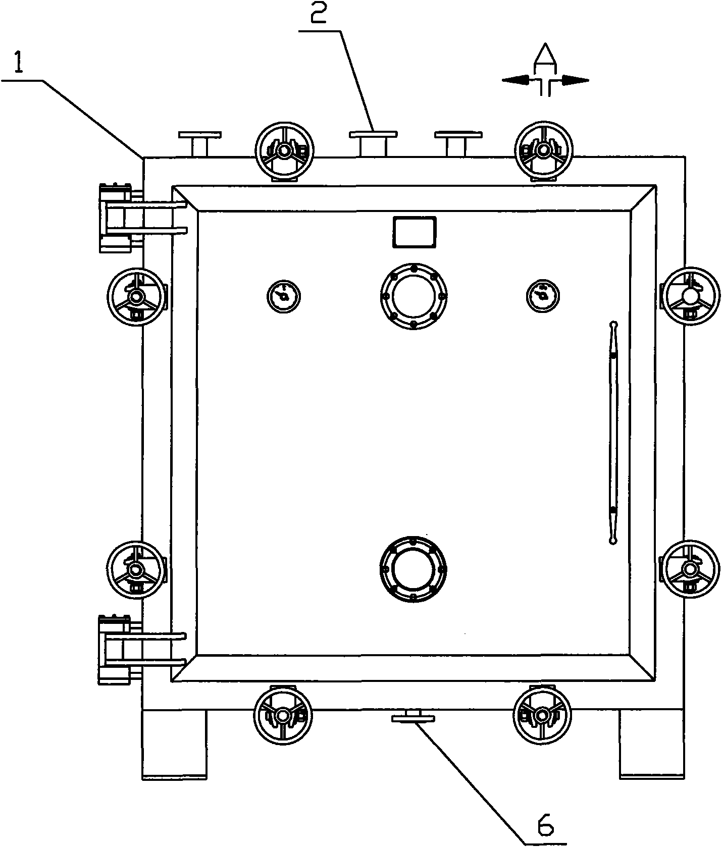
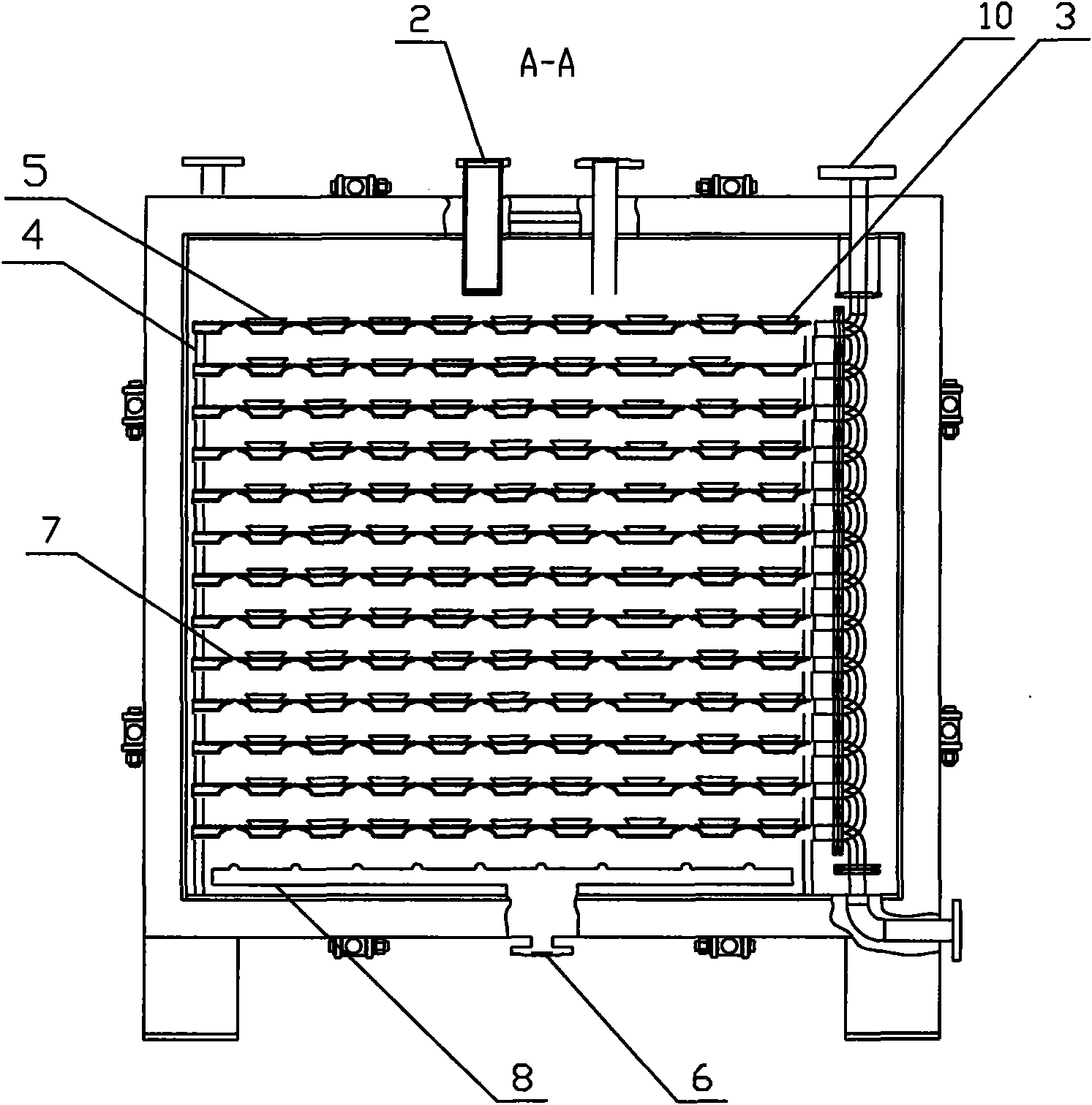
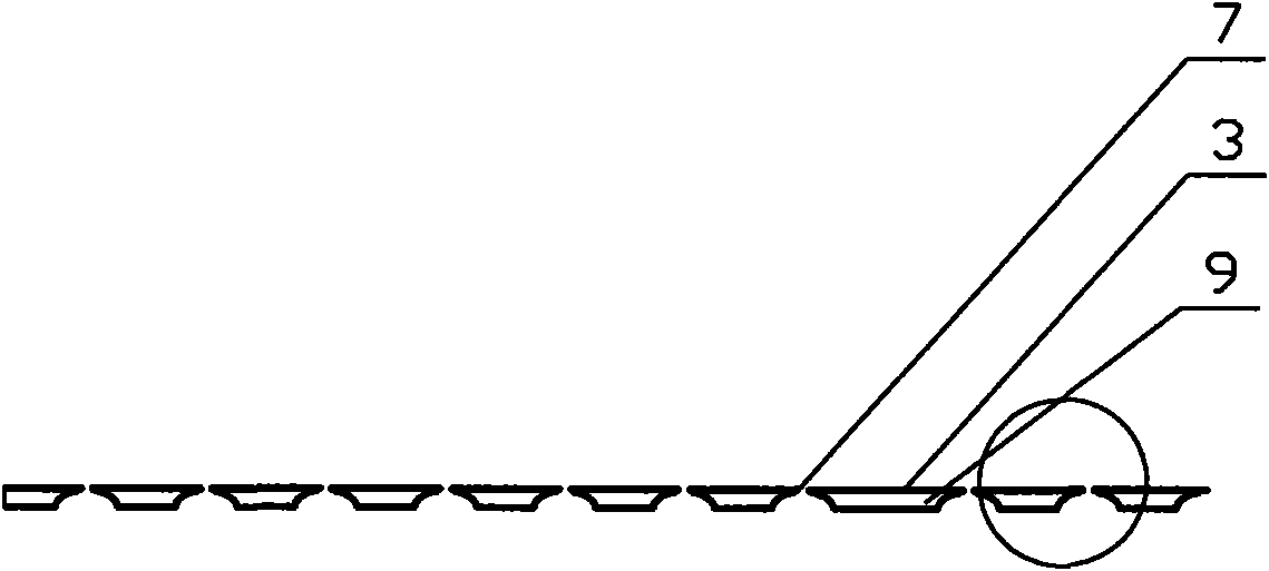
[0033] A new type of drying oven, such as figure 1 , figure 2 , image 3 , Figure 4 and Figure 5 As shown, it includes an oven shell 1, an air outlet 2, a flat panel 3, and a bracket 4 for placing the flat panel 3. The flat panel 3 is provided with a tray 5 for holding dried objects. The flat panel 3 is a breathable flat panel, and the drying box Have gas inlet 6 on it. The air-permeable flat panel is a flat panel with a heating device 9 attached.

[0034] In the above structure, there is a gas inlet pipe at the gas inlet 6 at the bottom of the drying box, and 72 equidistant circular air holes 11 with a diameter of 10 mm are evenly distributed on the gas-permeable flat plate with a length of 1320 mm and a width of 1000 mm. One end of the gas inlet pipe close to the air-permeable flat plate is connected with a gas distribution pipe 8, and the gas distribution pipe 8 is distributed with several small holes corresponding to the air holes on the air-permeable flat plate. ...

Embodiment 2

[0041] A new type of drying oven, such as figure 1 , figure 2 , image 3 , Figure 4 and Figure 5 As shown, it includes an oven shell 1, an air outlet 2, a flat panel 3, and a bracket 4 for placing the flat panel 3. The flat panel 3 is provided with a tray 5 for holding dried objects. The flat panel 3 is a breathable flat panel, and the drying box There is a gas inlet 6 on the top, and several air-permeable structures 7 are distributed on the air-permeable flat plate. The air-permeable structures 7 can be air holes, the air holes are circular, and the aperture of the air holes is 0.01mm. The air-permeable flat plate is Flat plate without additional heating means 9. One end of the gas inlet pipe close to the air-permeable flat plate is connected with a gas distribution pipe 8, and the gas distribution pipe 8 is distributed with several small holes corresponding to the air holes on the air-permeable flat plate. The oven shell is provided with a safety valve and spare port....

Embodiment 3

[0048] A new type of drying oven, such as figure 1 , figure 2 , image 3 , Figure 4 and Figure 5 As shown, it includes an oven shell 1, an air outlet 2, a flat panel 3, and a bracket 4 for placing the flat panel 3. The flat panel 3 is provided with a tray 5 for holding dried objects. The flat panel 3 is a breathable flat panel, and the drying box There is a gas inlet 6 on it, and at least one breathable structure 7 is distributed on the breathable flat plate. The breathable structure 7 is a breathable seam.

[0049] A kind of drying method of novel drying box, the steps are as follows:

[0050] The first step: open the drying box, put the substance to be heated in the tray 5 on the air-permeable flat plate in the drying box;

[0051] Step 2: Heat the air-permeable flat panel directly with the power supply, and then use the air-permeable flat panel to heat the dried objects in the tray 5 through heat conduction;

[0052] The third step: continue to dry, the ventilated...


PUM


Abstract

The invention discloses a novel drying oven. The novel drying oven comprises an oven shell, an air exhaustion hole, an air inlet, a flat plate and a support used for placing the flat plate, wherein a tray used for placing dried materials is arranged on the flat plate; the flat plate is an air-permeable type flat plate; and an air inlet tube is arranged on a drying box for inlet nitrogen or carbon dioxide or inert gases. In the novel drying oven, steam evaporated from wet materials to be dried can be quickly exhausted through an air-permeable structure due to the adoption of the air-permeable type flat plate, and the mass transfer is rapid, so steam pressure of the evaporated steam is lowered, the steam is not easily detained and condensed, and the drying speed is greatly improved; and under the condition of introducing a proper gas such as nitrogen into the air inlet tube, permeable holes can obviously improve the flowing and distribution of the nitrogen in the drying oven, so the steam at all parts of the drying oven can be quickly taken away along with the nitrogen, and the drying speed is further quickened.

Description

technical field [0001] The invention relates to a drying device and a drying method thereof, in particular to a novel drying oven and a drying method thereof. Background technique [0002] In the drying process of chemical substances that cannot be turned, vacuum drying ovens are often used for drying because the substances are usually heat-sensitive and the drying temperature cannot be too high, or the substances to be dried are porous and difficult to dry. Commonly used vacuum ovens have some obvious deficiencies. For example, traditional laboratory vacuum drying ovens use sidewall indirect heating, which leads to slow heat transfer and low efficiency under high vacuum conditions. Or although the heating plate of a large industrial oven can be directly heated, the heating plate is an integral piece (such as Figure 6 As shown), the mass transfer and heat transfer of water vapor in the oven are very limited. Water vapor is easy to stay or condense on the upper and lower pl...

Claims


Application Information

Patent Timeline
Patent Type & Authority Applications(China)
IPC IPC(8): F26B9/06F26B3/18F26B7/00F26B3/00F26B25/08
Inventor 王定军王中石
Owner 康纳新型材料(杭州)有限公司
Why Eureka
Try Eureka