
Rectifier grain, production method thereof and suction cup mould

A technology of rectifiers and grains, which is applied in semiconductor devices, semiconductor/solid-state device manufacturing, electrical components, etc., and can solve problems such as easy exposure of corners of square grains, small forward surge current, and poor impact resistance of products , to achieve the effect of increasing the reliability of tension and solder joints, enhancing the reverse withstand voltage performance, and reducing the damage of grains

Inactive Publication Date: 2012-10-17
GOOD ELECTRONICS WUHU
View PDF0 Cites 0 Cited by
  • Summary
  • Abstract
  • Description
  • Claims
  • Application Information

AI Technical Summary

Problems solved by technology

[0003] The area utilization rate of square grains on the same welding table is small. When the required forward current is a constant value, the small area leads to large resistance value, large forward DC voltage, high heat generation of the device, and poor product durability; The forward surge current is small, and the impact resistance of the product is poor; at the same time, because the angle of the square grain is 90°, the discharge effect of the tip is large, resulting in poor reverse voltage resistance of the product; when the rectifier is welded, the corner of the square grain easily exposed and damaged
[0004] When producing GPP grains, the mechanical cutting method of back cutting is adopted, the chip is not easy to be cut through, and the edge of the grain glass groove seal is easily damaged when it is split, which affects the electrical performance

Method used


Image

  • Rectifier grain, production method thereof and suction cup mould
  • Rectifier grain, production method thereof and suction cup mould
  • Rectifier grain, production method thereof and suction cup mould

Examples


Embodiment Construction

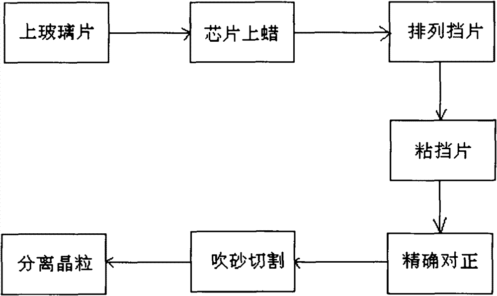
[0029] Such as figure 1 A method for producing rectifier crystal grains is shown, which includes firstly applying photoresist on the diffused silicon chip. The process is as follows: on the vacuum rotary machine, the terminal sucks the chip, drops a few drops of photoresist and rotates until uniform, and bakes. Dry; repeat the reverse side once, so that there is photoresist on both sides, and dry. Prepare two identical MASK films with graphic lines printed on them. The pattern formed by the graphic lines is a plurality of regular hexagons closely arranged in a honeycomb shape. Under the microscope, paste MASK films on both sides of the silicon chip respectively, align the patterns of the MASK films on both sides, expose and fix the silicon chip placed in the middle of the two MASK films at the same time, and then follow the fixed pattern on both sides of the silicon chip. Groove the pattern line, first open a shallow groove on the back of the silicon chip, apply photoresist o...


PUM


Abstract

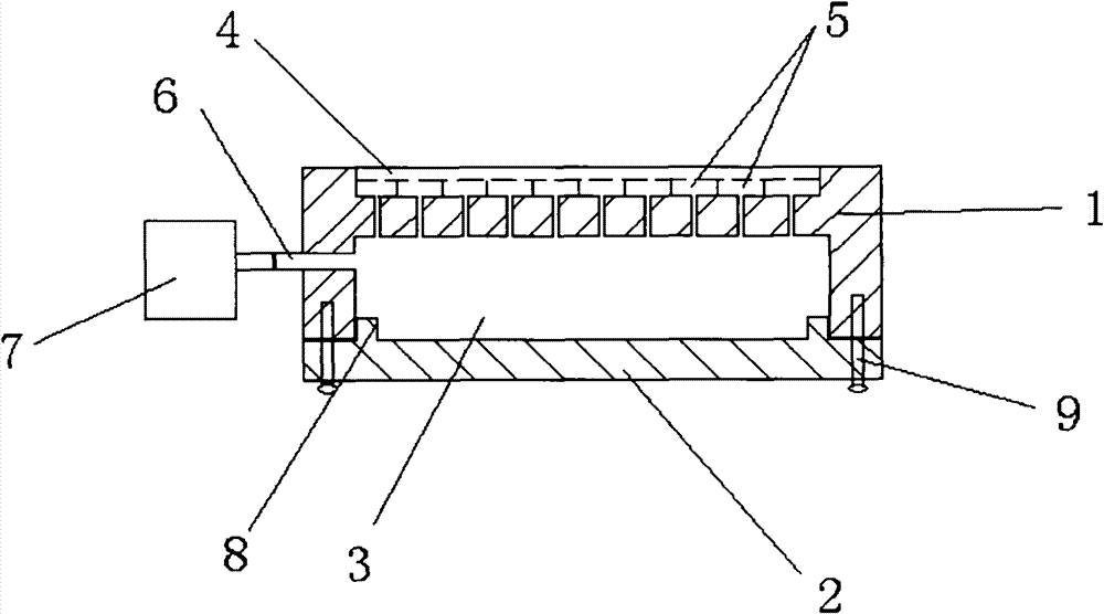
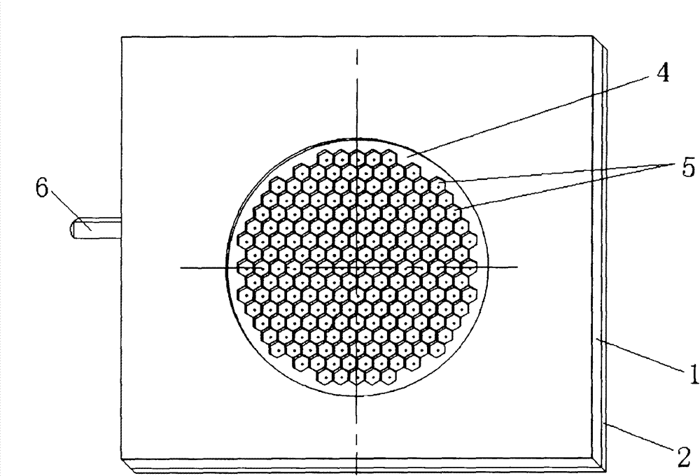
The invention discloses a rectifier grain, a production method thereof and a suction cup mould. The grain is in the shape of a regular hexagon. The production method for the grain comprises the following steps of: coating a photo-resist; adhering an MASK film; exposing; making a GPP film; arranging a glass sheet; waxing a chip; arranging a baffle; adhering the baffle; accurately aligning; cuttingby sand blasting; and separating the grain. The suction cup mould comprises an upper die and a lower die, wherein the upper and lower dies are detachably connected with each other so as to form a cavity which can be vacuumized; the upper surface of the upper die is provided with a notch; the bottom surface of the notch is provided with a plurality of regularly hexagonal counter bores which are cellular and arranged closely; and each counter bore is communicated with the cavity. By using the structure and the method, the rectifier grain, the production method and the suction cup mould have theadvantages that: firstly, the area utilization of the grain is improved, the product is durable, and the impact resistance is enhanced; secondly, the point discharge effect is reduced and the backward voltage resistance of the product is enhanced; and thirdly, the edge of a glass trench of the grain which is cut by the sand blasting method is tidy and the electrical performance is better protected.

Description

technical field [0001] The invention relates to a rectifier grain, and also relates to a production method of the rectifier grain and a suction cup mold for realizing the method. Background technique [0002] At present, the grain shape usually adopted by the rectifier is square. The production process of the square crystal grain (GPP grain) with glass passivation coating and connection is as follows: first, both sides of the diffused round silicon chip are coated with photoresist, and two transparent films (MASK films) are prepared. One of the films has a graphic line printed on it, which is a plurality of squares closely arranged. The other film has crosshairs printed on it. Overlap and match the two MASK films, and stick them firmly along one edge of the MASK films. Place the round silicon chip between two MASK films, exposure and fixation at the same time. The first groove is to open shallow grooves on both sides of the silicon chip, and the side of the chip with the...

Claims


Application Information

Patent Timeline
Patent Type & Authority Patents(China)
IPC IPC(8): H01L29/06H01L21/78H01L21/02H01L21/68
Inventor 陈鉴章
Owner GOOD ELECTRONICS WUHU
Learn More