
Method and device based on coal gasification for preparing hydrogen and separating CO2

A CO2 and coal gasification technology, applied in the field of coal gasification, can solve the problems of large quantity, disappearance, and negative impact on the ecological environment, and achieve the effects of high flow rate, long residence time, and sufficient chemical reaction time

Inactive Publication Date: 2010-09-15
SOUTHEAST UNIV
View PDF2 Cites 13 Cited by
  • Summary
  • Abstract
  • Description
  • Claims
  • Application Information

AI Technical Summary

Problems solved by technology

However, the conversion of coal to hydrogen energy will emit a large amount of CO 2 , the resulting greenhouse effect has a serious negative impact on the ecological environment, and the CO emitted during the coal-based hydrogen production process 2 The amount is quite huge, and the advantages of hydrogen as a clean energy source will disappear

Method used


Image

  • Method and device based on coal gasification for preparing hydrogen and separating CO2
  • Method and device based on coal gasification for preparing hydrogen and separating CO2

Examples


Embodiment 1

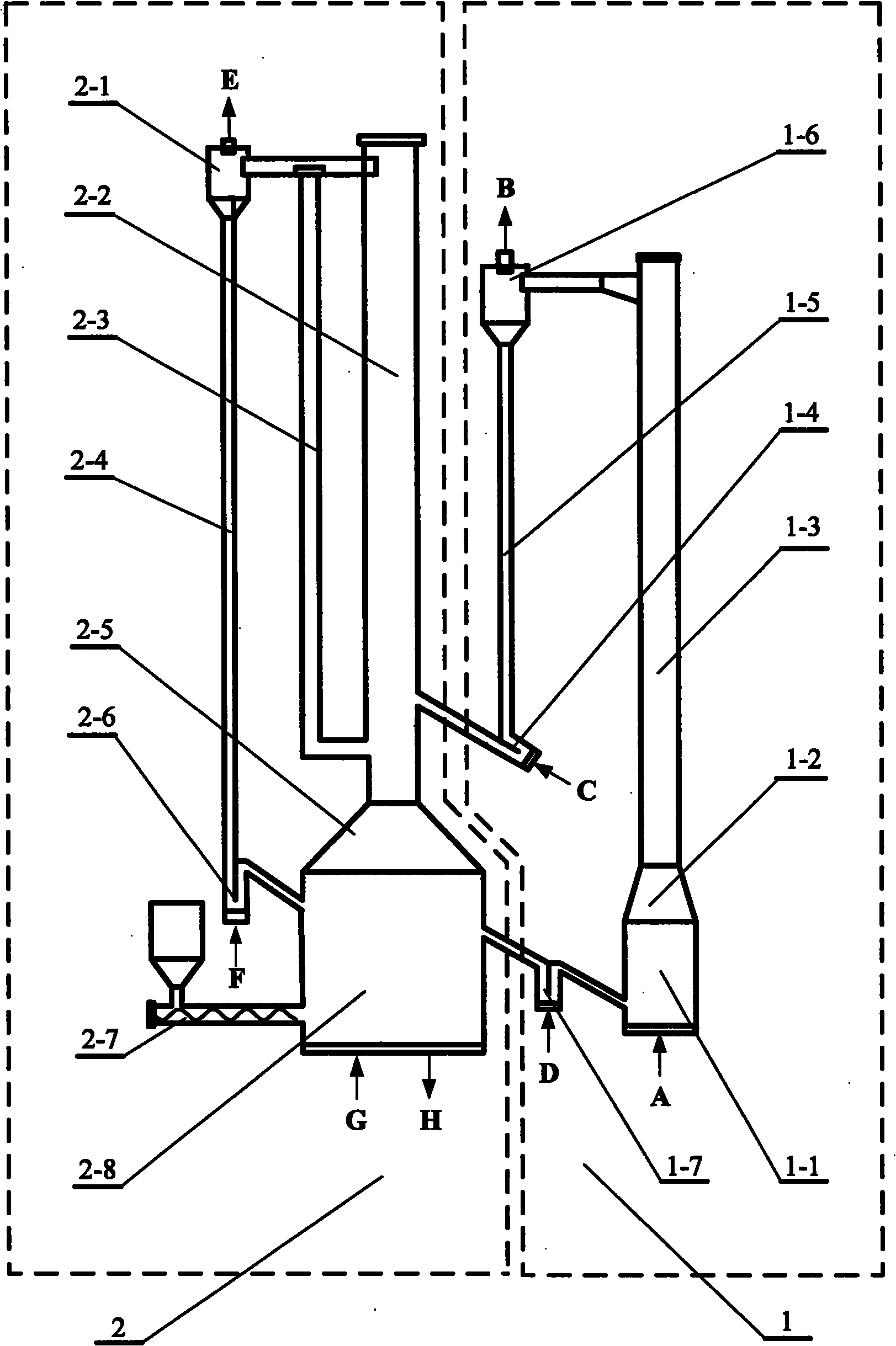
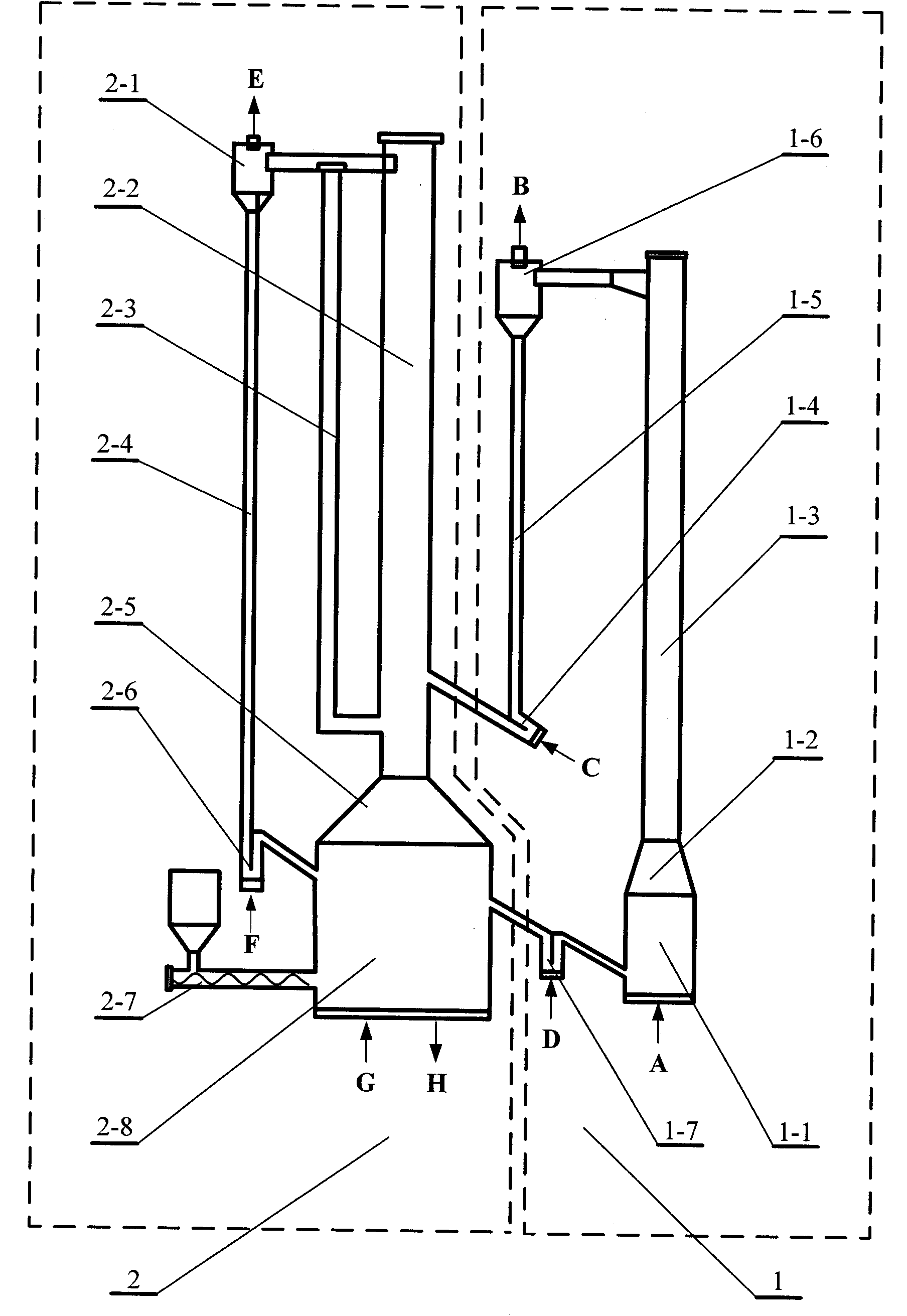
[0015] A method based on coal gasification to produce hydrogen and separate CO 2 method, the coal powder is fed into the mixed gasification reaction chamber 2-8 through the feeder 2-7, water vapor is passed into the lower end G of the mixed gasification reaction chamber, and the temperature of the mixed gasification reaction chamber 2-8 is controlled at 650 ℃ or so. Coal is pyrolyzed to form coke, which reacts with water vapor to generate H 2 , CO and CO 2 , where CO 2 Absorbed by CaO to generate CaCO 3 , due to CO 2 Can be absorbed and solidified by CaO, transformation reaction The equilibrium shifts to the right, and CO is continuously converted to CO by this reaction 2 , CO 2 Then it is absorbed and solidified by CaO; the gas leaving the mixed gasification reaction chamber 2-8 is H 2 and residual CO 2 , which enters the gasification bed riser 2-2 through the transition section 2-5 of the gasification reaction chamber. CaCO generated in mixed gasification reaction ...

Embodiment 2

[0017] A method for realizing the production of hydrogen and separation of CO based on coal gasification described in claim 1 2 The device is composed of gasification reaction fluidized bed 2 and calcium oxide regeneration reaction fluidized bed 1. Gasification reaction fluidized bed 2 is composed of mixed gasification reaction chamber 2-8, gasification reaction chamber transition section 2-5, gasification bed riser 2-2, hydrogen recirculation pipe 2-3, hydrogen separator 2-1 , feeding pipe 2-4, return chute 2-6 and feeder 2-7. The lower end of the gasification bed riser 2-2 is connected to the mixed gasification reaction chamber 2-8 through the mixed gasification reaction chamber transition section 2-5, and the upper end of the gasification bed riser 2-2 is connected to the hydrogen separator 2-1. The upper end is connected to the upper end of the hydrogen recirculation pipe 2-3, the lower end of the hydrogen recirculation pipe 2-3 is connected to the lower end of the gasifi...


PUM


Abstract

The invention discloses a method and a device based on coal gasification for preparing hydrogen and separating CO2. Coal and water vapor enter a gasification reaction chamber for gasification to obtain H2, CO and CO2. CO is converted to CO2 through a transformation reaction, and CO2 is absorbed by CaO to generate CaCO3. H2 and remnant CO2 enter a gasification bed rising pipe, and CaCO3 and remnant coke enter a calcium oxide regeneration reaction chamber. Pure oxide is introduced to the calcium oxide regeneration reaction chamber, the coke is burned with the oxide, CaCO3 is decomposed to CO2 and CaO, CO2 is separated with the CaO by a separator and is collected, and CaO enters the bottom of the gasification bed rising pipe to be raised by the H2 and the remnant CO2, and the CO2 is absorbed. Parts of the H2 and the CaO return to the bottom of the gasification bed rising pipe through a recirculating pipe. The other part of the H2 and the CaO are separated by the separator to obtain purified H2, and the separated CaO returns to the gasification reaction chamber for cyclic utilization.

Description

technical field [0001] The invention relates to a method and device for coal gasification, in particular to a method for producing hydrogen and separating CO by gasification of coal and steam. 2 methods and devices. Background technique [0002] One of the sustainable development strategies of energy utilization is to realize the efficient and clean utilization of energy. As a clean energy source, hydrogen is accompanied by water in the process of energy conversion, which can truly achieve zero emission of pollutants, and can be directly burned for power generation, heat supply, or used as vehicle fuel. As the global "oil security", "greenhouse gas emission greenhouse effect" and "environmental protection" issues become more and more serious, reduce the dependence on oil, strengthen the capture and storage of carbon dioxide, and reduce the impact on the environment. In the future In the sustainable energy system, hydrogen is expected to become an important energy carrier a...

Claims


Application Information

Patent Timeline
IPC IPC(8): C01B3/06C01B3/56C10J3/54C10J3/56C01B3/12C01B31/20C01B32/50
CPCY02E60/36Y02A50/20
Inventor 向文国陈时熠薛志鹏
Owner SOUTHEAST UNIV
Learn More