
Synchronous rectifying circuit structure for high-frequency switch power supply

A high-frequency switching power supply and synchronous rectification technology, applied in the electrical field, can solve the problems of connection, heat dissipation and extra heat, and achieve the effects of improving performance, reducing lead loss, and reducing lead length

Inactive Publication Date: 2012-07-18
XI AN JIAOTONG UNIV
View PDF0 Cites 0 Cited by
  • Summary
  • Abstract
  • Description
  • Claims
  • Application Information

AI Technical Summary

Problems solved by technology

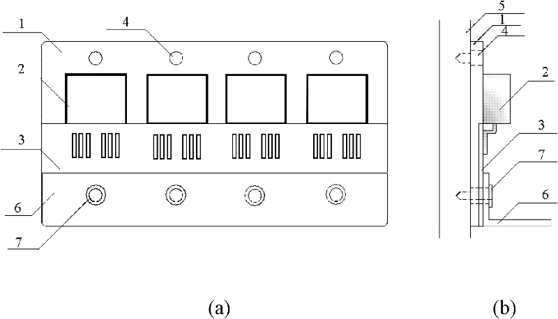
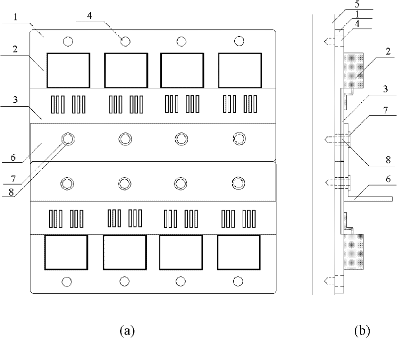
[0004] Aiming at the current problems of connection, heat dissipation and extra heat in the structure and connection mode of the synchronous rectification circuit of the switching power supply under the condition of large current, the present invention proposes a parallel structure of field effect transistors based on a copper base plate and field effect transistors and high frequency Transformer and radiator connection mode, in the full-wave synchronous rectification circuit using the common drain connection method, the drains of multiple surface mount type field effect transistors are welded to the copper base plate, and the gates and sources are connected to the printed circuit board welding, and then connected to the output terminal of the high-frequency transformer

Method used


Image

  • Synchronous rectifying circuit structure for high-frequency switch power supply
  • Synchronous rectifying circuit structure for high-frequency switch power supply
  • Synchronous rectifying circuit structure for high-frequency switch power supply

Examples


Embodiment Construction

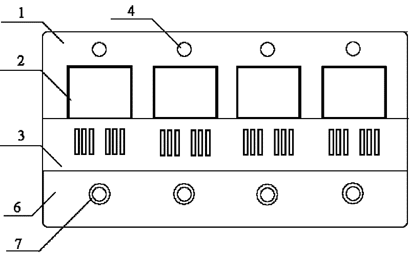
[0009] refer to figure 1 As shown, it includes a copper base plate 1, a surface mount package field effect transistor 2, and a printed circuit board 3. A groove is provided at one end of the copper base plate 1, and the printed circuit board 3 is installed in the groove of the copper base plate 1. The printed circuit board 3 The height of the upper surface is the same as that of the copper base plate. The other end of the copper base plate 1 is connected to the drain of the field effect transistor 2, and the gate and source of the field effect transistor 2 are connected to the printed circuit board 3. The number of field effect transistors used in the circuit Adjust according to needs, the copper base plate 3 is connected with the radiator 5, and the radiator is used as the output positive bus bar at the same time, a high-frequency transformer is installed on the printed circuit board 3, and the output terminal 6 of the high-frequency transformer is connected to the source of t...


PUM


Abstract

The invention discloses a synchronous rectifying circuit structure for a high-frequency switch power supply and provides a field effect transistor parallel connection structure based on a copper base plate and a connecting way of a field effect transistor, a high-frequency transformer and a heat radiator. In a full-wave synchronous rectifying circuit adopting a common drain electrode connecting method, drain electrodes of a plurality of surface mounting type encapsulated field effect transistors are welded with a copper base plate; and grid electrodes and source electrodes are welded with a printed circuit board and connected with an output terminal of the high-frequency transformer. The copper base plate provided with the field effect transistors is connected with the heat radiator in use, and the heat radiator is meanwhile used as an output positive bus. Finally, the terminal of the high-frequency transformer is in compression joint with the printed circuit board, the copper base plate and the heat radiator to meanwhile play roles of fixation and support.

Description

technical field [0001] The invention belongs to the field of electrical technology, and relates to a synchronous rectification circuit structure for a high-frequency switching power supply. Background technique [0002] Switching power supplies based on high-frequency conversion technology have been widely used due to their advantages of small size, light weight and high efficiency. When the output voltage is low, the efficiency of this type of power supply is lower than that of a switching power supply with a higher output voltage due to the influence of the conduction voltage drop of the diode in the high-frequency rectification part of the converter. In order to reduce the loss of rectifier diodes and improve device efficiency, synchronous rectification technology is widely used at present, that is, field effect transistors are used instead of diodes to complete the rectification function. In the switching power supply with low voltage output, in order to reduce the numb...

Claims


Application Information

Patent Timeline
Patent Type & Authority Patents(China)
IPC IPC(8): H02M7/521H05K7/20
Inventor 裴云庆张维民邓明海
Owner XI AN JIAOTONG UNIV
Learn More