Laminated optical film, liquid crystal panel, and liquid crystal display
A liquid crystal display device and optical film technology, applied in optics, optical elements, nonlinear optics, etc., can solve the problems of mixing foreign matter, increase in the manufacturing process of liquid crystal display device, abnormality, etc., and achieve the effect of simplifying the manufacturing process and realizing thinning
- Summary
- Abstract
- Description
- Claims
- Application Information
AI Technical Summary
Problems solved by technology
Method used
Image
Examples
Embodiment 1
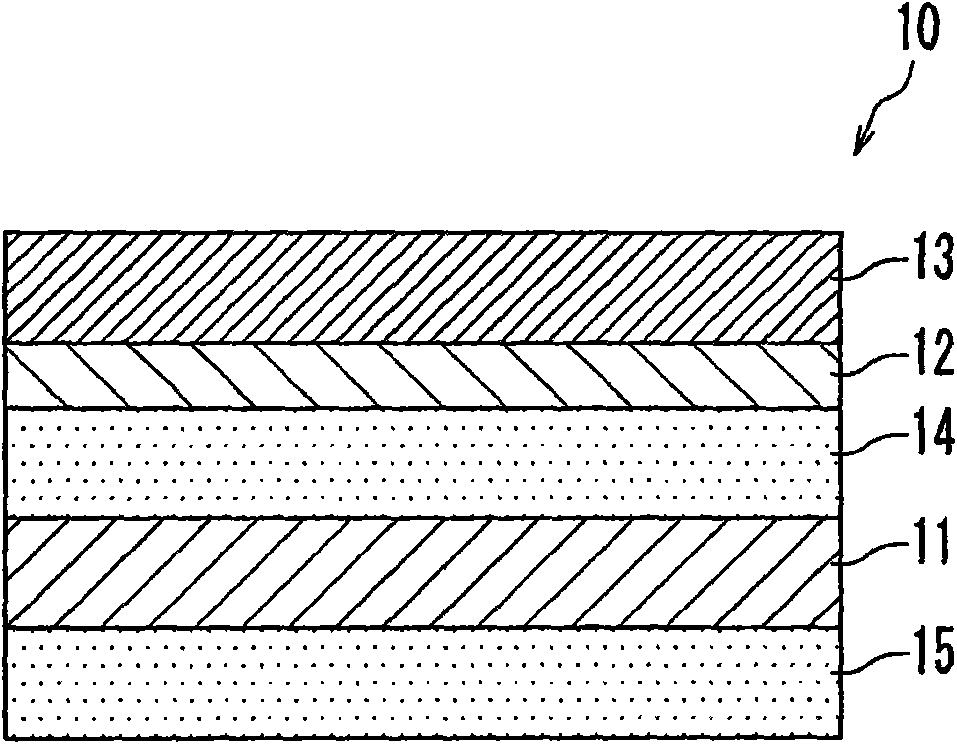
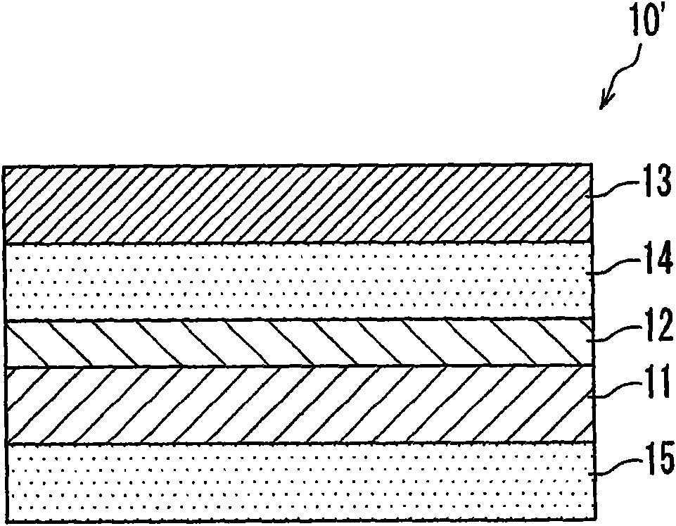
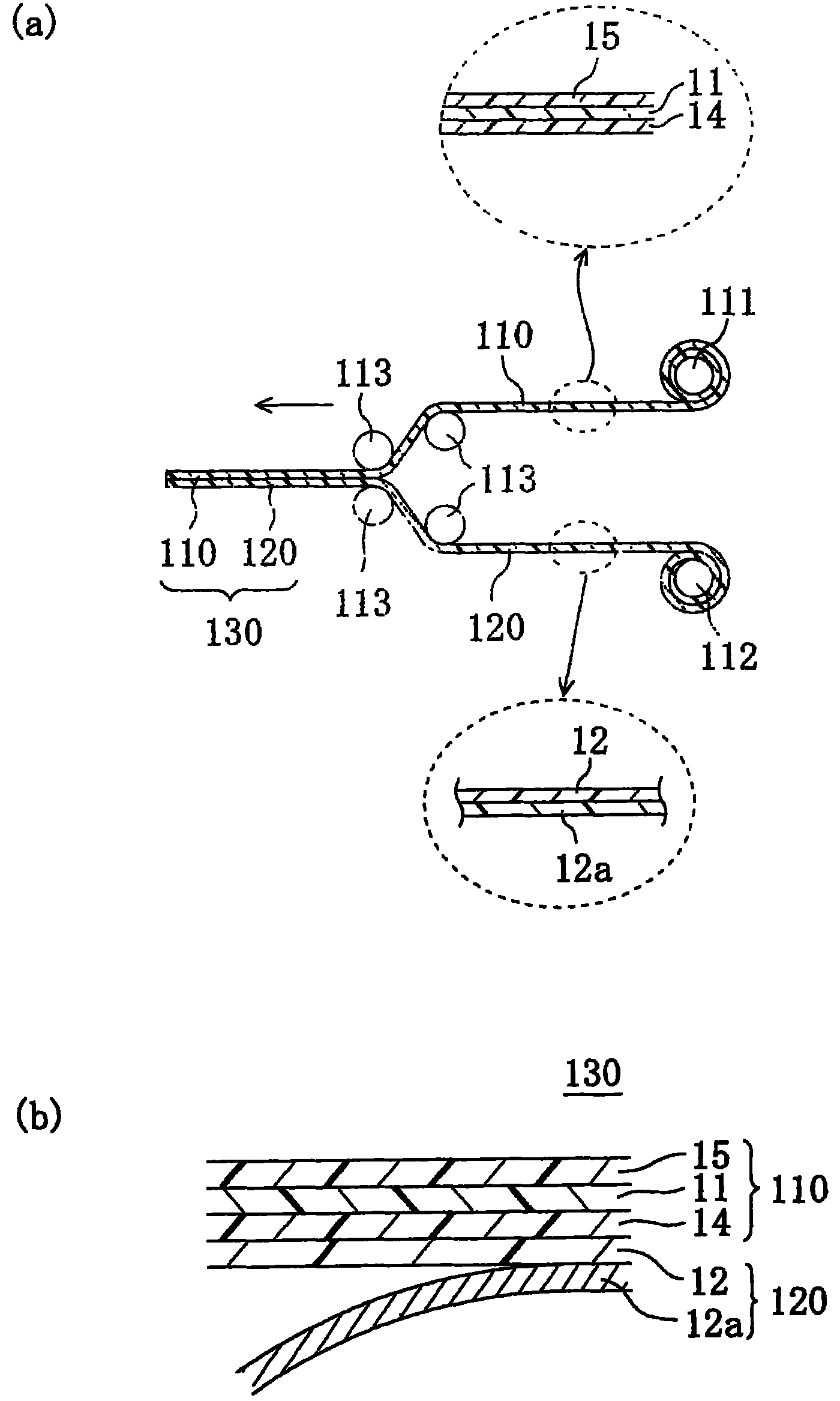
[0122] (Production of retardation layer)
[0123] After forming a polyvinyl alcohol film (0.1 μm in thickness) on the surface of a substrate (TAC film, 40 μm in thickness), rubbing treatment was performed on the surface of the polyvinyl alcohol film in a direction 45° to the longitudinal direction of the substrate using an orientation cloth , making an orientation substrate.
[0124] Next, 10 g of polymerizable liquid crystals (manufactured by BASF Corporation, trade name Paliocolor LC242) exhibiting a nematic liquid crystal phase, and a photopolymerization initiator for the polymerizable liquid crystal compound (manufactured by Ciba Specialty Chemicals, 0.5 g of Irgacure 907 (trade name, containing 1% of benzotriazole-based ultraviolet absorber) was dissolved in 40 g of toluene to prepare a coating solution. Then, this coating liquid was applied to the surface of the alignment substrate obtained above by a bar coater, and then heated and dried at 90° C. for 2 minutes to alig...
Embodiment 2
[0133] (production of polarizer)
[0134] A polyvinyl alcohol film (average degree of polymerization: 2400, degree of saponification: 99.9%) having a thickness of 80 μm was immersed in pure water at 30° C. to swell. Next, it was stretched 2.5 times while being immersed in a dyeing bath containing iodine and potassium iodide at 30° C. for 60 seconds for dyeing. Then, it was stretched 2.3 times while being immersed in a boric acid aqueous solution at 40° C. for 60 seconds. Next, it was immersed in an aqueous solution having a potassium iodide concentration of 5% at 30° C. for 5 seconds. Thereafter, it was dried at 50° C. for 4 minutes to obtain a polarizing plate (thickness: 26 μm).
[0135] (Manufacturing of laminated optical film)
[0136] On the TAC film side of the TAC film formed with the hard coat layer obtained in Example 1, a polyester-based adhesive (manufactured by Takeda Pharmaceutical Co., Ltd.; trade name: Takenate A310 / Takelac A-3; solvent: ethyl acetate ; Thic...
reference example 1
[0147] (Manufacturing of laminated optical film)
[0148] A laminated optical film was obtained in the same manner as in Example 1 except that the retardation layer was not laminated.
[0149] Compared with the laminated optical film of Comparative Example 1, the laminated optical films of Example 1 and Example 2 of the present invention were remarkably thinner. As a result, the laminated optical film of the present invention can contribute to thinning of liquid crystal panels and liquid crystal display devices.
PUM
| Property | Measurement | Unit |
|---|---|---|
| thickness | aaaaa | aaaaa |
| glass transition temperature | aaaaa | aaaaa |
| thickness | aaaaa | aaaaa |
Abstract
Description
Claims
Application Information
 - R&D
- Intellectual Property
- Life Sciences
- Materials
- Tech Scout
- Unparalleled Data Quality
- Higher Quality Content
- 60% Fewer Hallucinations
Browse by: Latest US Patents, China's latest patents, Technical Efficacy Thesaurus, Application Domain, Technology Topic, Popular Technical Reports.
© 2025 PatSnap. All rights reserved.Legal|Privacy policy|Modern Slavery Act Transparency Statement|Sitemap|About US| Contact US: help@patsnap.com


