
Ion implantation method

An ion implantation and ion beam technology, which is used in ion implantation plating, coating, electrical components, etc., can solve the problems of inability to maintain the stability of the ion beam, high difficulty in beam adjustment, and low beam utilization efficiency. Optical properties, reduced overall difficulty, easy-to-control effects

Active Publication Date: 2010-09-22
KINGSTONE SEMICONDUCTOR LIMITED COMPANY
View PDF0 Cites 4 Cited by
  • Summary
  • Abstract
  • Description
  • Claims
  • Application Information

AI Technical Summary

Problems solved by technology

[0006] The technical problem to be solved by the present invention is to overcome the defects of the ion implantation method in the prior art that the beam adjustment is difficult, the stability of the ion beam cannot be maintained, and the beam utilization efficiency is low, and to provide an ion implantation method that is relatively difficult to adjust the beam current. An ion implantation method that is low in cost, can maintain good stability of the ion beam, and has high beam utilization efficiency

Method used


Image

  • Ion implantation method
  • Ion implantation method
  • Ion implantation method

Examples


Embodiment 1

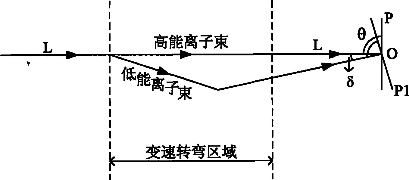
[0023] Such as figure 2 As shown, the low-energy ion beam is deflected at an appropriate angle twice in the variable-speed turning region through the electric effect or magnetic effect, so that it is also at the implantation position O of the workpiece compared with the non-deflected high-energy ion beam , but the implantation angle is deflected by δ. Correspondingly, the workpiece is rotated by the same angle δ to reach the first station P1. The first station P1 enables the low-energy ion beam to remain at the preset incident angle θ at The injection is completed at the injection position O of the workpiece.

Embodiment 2

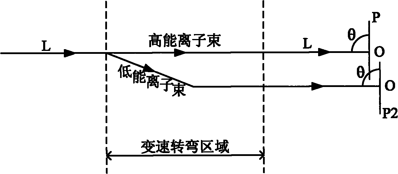
[0025] Such as image 3 As shown, by means of electric effect or magnetic effect, the low-energy ion beam is deflected at an appropriate angle twice in the variable-speed turning region, so that it has the same implantation angle θ compared with the non-deflected high-energy ion beam, but At this time, the alignment is no longer the implantation position O of the workpiece. Correspondingly, the workpiece is translated to the second station P2, and the second station P2 enables the low-energy ion beam to remain at the preset incident angle θ The injection is completed at the injection position O of the workpiece.

Embodiment 3

[0027] Such as Figure 4 As shown, through the electric effect or magnetic effect, the low-energy ion beam is deflected at an appropriate angle in the variable-speed turning area, so that compared with the high-energy ion beam without deflection, not only the implantation angle is deflected, but also the It is no longer aligned with the implantation position O of the workpiece. Correspondingly, the workpiece is rotated angularly and translated to make it reach the third station P3. The third station P3 enables the low-energy ion beam to still maintain the The preset incident angle θ completes the implantation at the implantation position O of the workpiece.


PUM


Abstract

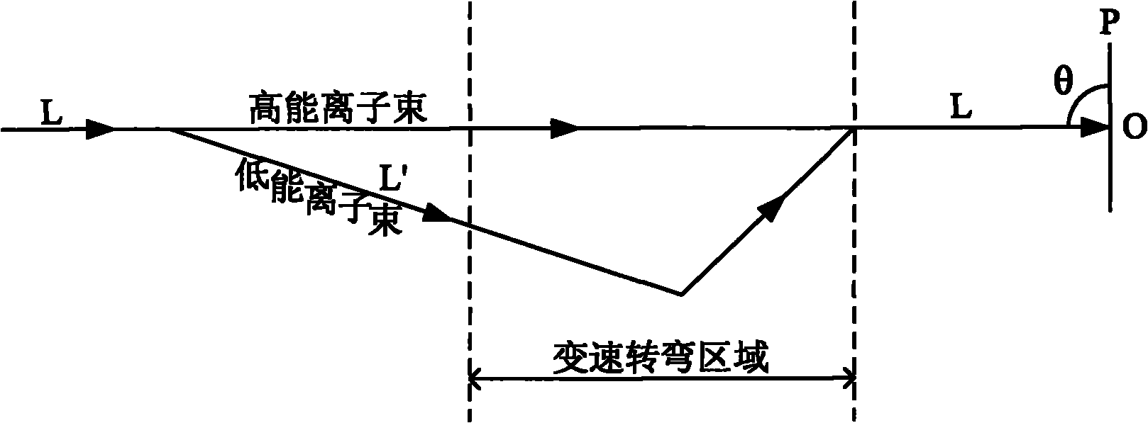
The invention discloses an ion implantation method. In the method, high energy ion beams in ion beams which are emergent along a straight path are implanted in a workpiece at a preset incident angle, the workpiece is arranged at a preset station on the straight path, low energy ion beams in the ion beams are subjected to deflection at least once by electrical effect or magnetic effect, the position and / or the angle of the workpiece are / is adjusted relative to the preset station to enable the low energy ion beams to be implanted in the workpiece at a preset emergent angle, and the implantation positions of the low energy ion beams and the high energy ion beams on the workpiece are the same. The method does not regulate the beam path in front of a speedchange turning area, thus lowering the difficulty in beam adjustment, maintaining beam optical characteristics better, ensuring good stability of ion beams, facilitating beam control, shortening adjustment time consumed by beam path switch greatly and improving beam utilization ratio.

Description

technical field [0001] The invention relates to a semiconductor manufacturing method, in particular to an ion implantation method. Background technique [0002] As the production of semiconductor products gradually tends to larger semiconductor wafers (from 8 inches to 12 inches, even 18 inches), the current single wafer process (processing one wafer at a time) has been well adopted. [0003] Ion implantation is a process of doping impurities in a semiconductor substrate to change the electrical and material properties of the substrate. Ion implantation is an essential process for wafer doping in today's semiconductor industry. In ion implantation, due to the consideration of reducing the influence of the channeling effect, when performing ion implantation on the wafer, it is necessary to make an angle between the wafer and the ion beam according to the direction of the crystal lattice of the wafer. Moreover, in the single-wafer process, due to the strict requirements on t...

Claims


Application Information

Patent Timeline
Patent Type & Authority Applications(China)
IPC IPC(8): C23C14/48H01L21/265
Inventor 钱锋
Owner KINGSTONE SEMICONDUCTOR LIMITED COMPANY
Learn More