Method and apparatus for recording and reproducing optical information, and recording medium

A technology for recording and reproducing devices and recording media, applied to optical recording media, recording/reproducing with optical methods, data recording, etc.

Inactive Publication Date: 2010-09-22
HITACHI CONSUMER ELECTRONICS CORP
View PDF4 Cites 4 Cited by
  • Summary
  • Abstract
  • Description
  • Claims
  • Application Information

AI Technical Summary

Problems solved by technology

In a normal lens, when light is emitted out of the lens, it is refracted at the interface with air whose refractive index is smaller than that of the lens, so NA cannot be set to 1 or more

Method used


Image

  • Method and apparatus for recording and reproducing optical information, and recording medium
  • Method and apparatus for recording and reproducing optical information, and recording medium
  • Method and apparatus for recording and reproducing optical information, and recording medium

Examples


Embodiment 1

[0048] As a first aspect of the embodiment, a configuration example of an optical disk drive having a function of detecting an event such as a change in ambient temperature or a temperature change of laser light and performing adjustment of recording power and super-resolution reproduction power will be described.

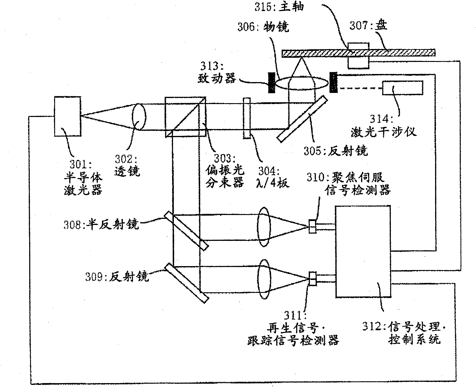
[0049]FIG. 3(A) shows a configuration diagram of a driver. Laser light is emitted from a semiconductor laser 301 and passed through a lens 302 to become parallel light. The parallel light passes through the polarizing beam splitter 303 . At this time, the laser beam emitted from the semiconductor laser 301 is linearly polarized light, but the direction of the polarized beam splitter 303 is adjusted in advance so that the polarized light direction completely passes through the polarized beam splitter 303 . The laser light is converted into circularly polarized light by the λ / 4 plate 304 , passes through the reflector 305 and the objective lens 306 , and becomes a f...

Embodiment 2

[0069] Here, a case where the drive structure is substantially the same as that of the first embodiment, but that uneven data is provided on the disc will be described.

[0070] A write-once super-resolution disc is inserted into this drive. Here, the part up to the detection of the recommended recording and reproduction conditions is the same as that of the first embodiment.

[0071] Then, the optical head was moved to an area with a radius of 25.1 to 25.2 mm on the disk, where a data row consisting of 2T to 8T long unevenness was formed. The reproduction power is varied at intervals of 0.1 mW within ±20% of the recommended reproduction power, and the reproduction power at which the jitter of the uneven data is minimized is defined as the provisional super-resolution reproduction power Psr'. The value of Psr' at this time and the reproduced signal are recorded in the flash memory provided in the control system 312.

[0072] Then, the light spot is moved to the recording and...

Embodiment 3

[0081] A method for confirming the effects of this embodiment with an optical disc tester will be described.

[0082] Figure 4 A block diagram showing a disc tester. Functions and operations are almost the same as those of the optical disc drive shown in the first embodiment. The difference is that the reproduced signal and servo signal can be observed through the oscilloscope 416; the operation of the tester, the bias adjustment of the servo signal, the position of the optical head, the timing of laser irradiation, the waveform or power of laser irradiation, and other conditions can be controlled through the control computer 417. .

[0083] A write-once super-resolution disc 407 is mounted on this tester, and a spindle 415 is rotated to fix a light spot at a predetermined position on the disc by a servo system.

[0084] The disk used is a disk that has not yet been shipped as a product, and the recommended recording and reproduction conditions described in the first and s...


PUM

PropertyMeasurementUnit
thicknessaaaaaaaaaa

Abstract

Ordinary optical disks need the resetting of recording conditions in the course of recording to cope with changes in ambient temperature, laser temperature, and medium's recording sensitivity. Optical disks for super-resolution reproduction which are intended to reproduce record marks smaller than the optical resolution, thereby increasing the recording density, need the resetting of recording conditions as well as the condition of super-resolution reproduction because the quality of reproduced signals depends largely on the power for super-resolution reproduction. The power for recording as well as the power for super-resolution reproduction is therefore changed in the course of test recording to detect the deviation from the optimum value of the recording condition to obtain the optimum recording power. In this case, it is also desirable to change the power for super-resolution reproduction in proportion to the power for recording.

Description

technical field [0001] The present invention relates to the technology of large-capacity optical discs, especially in super-resolution optical discs with a recording density exceeding the diffraction limit of light, a method required for determining the optimum conditions for recording information on the disc and a method for realizing the same installation. Background technique [0002] Currently, as a large-capacity information recording technology, research and development of a high-density optical recording technology capable of storing more information per unit area is underway. In the currently commercialized optical disc technology, laser light is focused on the disc through a lens to reproduce and / or record data recorded on the disc. In order to densify data, a technique of reducing the size of a converged laser spot has been developed so far. It is known that when the wavelength of the light source is λ and the numerical aperture of the objective lens is NA, the s...

Claims


Application Information

Patent Timeline
Patent Type & Authority Applications(China)
IPC IPC(8): G11B7/24
CPCG11B7/1267G11B7/0037
Inventor 新谷俊通峰邑浩行江藤宗一郎
Owner HITACHI CONSUMER ELECTRONICS CORP
Why Eureka
Try Eureka