Reinforcing heat transfer method and heat exchange coil tube component for evaporative heat exchanger

A technology for strengthening heat transfer and heat exchange coils, which can be applied to tubular elements, heat exchange equipment, lighting and heating equipment, etc., and can solve the problems of low gas cooling heat transfer coefficient, increase in cost, height of the whole machine and increase in manufacturing cost. , to achieve the effect of reducing contact thermal resistance, saving space, and low processing cost

Inactive Publication Date: 2010-09-29
BAC DALIAN
View PDF2 Cites 14 Cited by
  • Summary
  • Abstract
  • Description
  • Claims
  • Application Information

AI Technical Summary

Problems solved by technology

However, limited by processing conditions and other factors, the heat exchange coils currently used are mainly in the form of bare tubes. In many cases in practical applications, the thermal working fluid is in an overheated state, and the superheated gas working fluid entering the condenser coil is first It needs to be cooled to the saturated vapor temperature, and then condensation can be realized, and the latent heat is released to complete the enthalpy reduction process; in addition, there are many mixed gas condensation processes, due to the low heat transfer coefficient of gas cooling, a large part of the coil area must be consumed to meet the gas The cooling process of the working fluid results in a larger volume of the coil, which takes up a lot of space when installed in the evaporative heat exchanger box, resulting in a lot of increased costs for equipment transportation, installation, and space occupation of the operating system.
The existing evaporative heat exchanger, especially for the low convective heat transfer coefficient of the gas working medium in the tube, is currently applied better way to install a set of outer finned tubes at the exhaust port, using the exhausted air flow The advantage of pre-cooling the gaseous superheated refrigerant is that the additional energy consumption is small, but the overall height and manufacturing cost are significantly increased

Method used


Image

  • Reinforcing heat transfer method and heat exchange coil tube component for evaporative heat exchanger
  • Reinforcing heat transfer method and heat exchange coil tube component for evaporative heat exchanger
  • Reinforcing heat transfer method and heat exchange coil tube component for evaporative heat exchanger

Examples


Embodiment 1

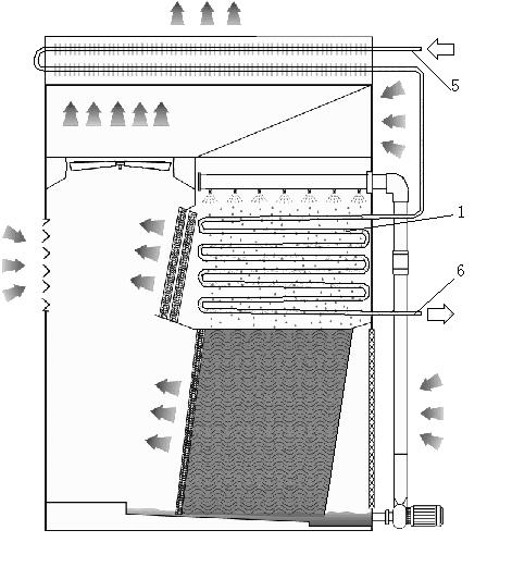
[0020] Example 1 : A refrigeration system using ammonia refrigerant, the condensation temperature is 35.7°C, the superheat of the ammonia vapor at the outlet of the compressor is 40°C, and the evaporative condenser adopts figure 2 Structure, upper coil and lower packing form, heat exchange coil assembly is composed of coil tube bundle 1, partition plate 2 arranged by tube bundle, spacer tube 3, tube bundle header 4, inlet 5 and outlet 6 connecting pipes, and other supporting parts , a total of 10 tube passes, the heat exchange area of ​​the outer surface of the coil is 250m 2 , the proportion of convective heat transfer heat resistance in the superheated tube accounts for 75%.

[0021] The heat transfer effect is enhanced by installing enhanced heat transfer components in the coil tube bundles of some tube passes (the first and second tube passes at the entrance of the coil). Specifically, the coils used in the first and second tubes at the coil inlet are as follows: Fig...

Embodiment 2

[0023] Example 2 : Refrigeration system using freon (R22a) refrigerant, the steam superheat at the outlet of the compressor is 30°C, the condensation temperature is 40°C, and the evaporative condenser adopts figure 2 Structure, upper coil and lower packing form, heat exchange coil assembly is composed of coil tube bundle 1, partition plate 2 arranged by tube bundle, spacer tube 3, tube bundle header 4, inlet 5 and outlet 6 connecting pipes, and other supporting parts , a total of 10 tube passes, the heat exchange area of ​​the outer surface of the coil is 250m 2 , the proportion of convective heat transfer heat resistance in the superheated tube accounts for 70%.

[0024] The heat transfer effect is enhanced by installing enhanced heat transfer components in the coil tube bundles of some tube passes (the first and second tube passes at the entrance of the coil). Specifically, the coils used in the first and second tubes at the coil inlet are as follows: Figure 4 , 5 As ...

Embodiment 3

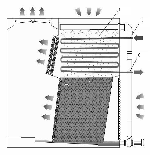
[0026] Example 3 : Compressor outlet air cooler, using figure 1 Full-coil evaporative cooling heater, the heat exchange coil assembly is composed of coil tube bundle 1, partition board 2 arranged by tube bundle, spacer tube 3, tube bundle header 4, inlet 5 and outlet 6, and other supporting parts , The coil structure is a U-shaped structure with 2 tubes, 8 loops, and the tube length is 3.5m.

[0027] The enhanced heat transfer components are installed in the coil tube bundles of all tubes to enhance the heat transfer efficiency of the gas in the tubes. Specific coils such as Figure 4 , 5 As shown, the tube body 7 of the coil is a stainless steel tube with a geometric dimension of Φ32×1.0 (mm), and a stainless steel core tube 8 is installed in the tube body. The geometric dimension of the core tube is Φ8×1 (mm), and the distance between the tube body and the core tube There are 9 inner fins installed between them, and the finning ratio is 7. The parameters of other struct...


PUM


Abstract

The invention belongs to the field of evaporative heat exchange equipment, and relates to a reinforcing heat transfer method for an evaporative heat exchanger. Gaseous working media which are subjected to heat exchange by a coil tube flow into an upper connector of the coil tube, condensed and cooled working media outflow from a lower connector, and a reinforcing heat transfer component is additionally arranged in tube bundles of the coil tube of part or all of tube passes to improve the heat transfer efficiency. In the coil tube component of the invention, the coil tube is subjected to the processing of an integrally-finned expansion heat exchange surface partially or completely according to the properties of the condensed or cooled working media and the requirement of tube resistance; fins are machined by made-to-measure dies independently, and structures and shapes of the fins can be adjusted; the fins are arranged in a direct-insert mode, are convenient, flexible and have low manufacturing cost; the support action supplied by a core tube can ensure the contact area between the fins and an outer tube fully, and reduce the contact heat resistance of the internal fins furthest. The coil tube component adopting the integrally-finned reinforcing heat transfer component has the advantages of occupied space saving, large heat exchange rate of unit volume, high heat exchange efficiency and small appearance dimensions of a complete machine.

Description

technical field [0001] The invention belongs to the field of evaporative heat exchange equipment, and particularly relates to a heat exchange method thereof, and in addition, the invention also relates to a heat exchange coil assembly thereof. Background technique [0002] Evaporative heat exchangers include evaporative condensers and evaporative fluid coolers, such as figure 1 , figure 2 and image 3 As shown, it is a heat exchange equipment that combines traditional water-cooled heat exchange equipment with a circulating water cooling tower. By spraying low-temperature circulating water on the surface of the heat exchange coil, the heat exchange process of the working medium inside and outside the tube is realized, and the forced convection The dry and cold air evaporates part of the spray water, maintains a lower circulating water temperature, and finally takes away the heat released by the hot fluid in the pipe. Because of its small water consumption, energy saving, ...

Claims


Application Information

Patent Timeline
Patent Type & Authority Applications(China)
IPC IPC(8): F28F1/40
Inventor 周兴东徐雄冠邓凯翔江磊姜文俊
Owner BAC DALIAN
Why Eureka
Try Eureka