


Quick Research
Generate reliable direction feasibility study reports for your R&D in just a few steps.

Technical Q&A
Discover and master advanced knowledge NOW. Basics, ideas, possibilities, all at once.

Find Solutions
As an expert in R&D theories, this can generate solutions to your technical problems instantly.

Evaluate Feasibility
Analyze your overall solution with one click, know your potential R&D risks in advance.

Monitor Landscape
Get weekly tech updates, stay abreast of the latest tech innovations and key insights.
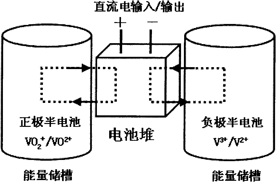
Bipolar plate frame and galvanic pile of flow battery
A liquid flow battery and bipolar plate technology, which is applied to battery electrodes, fuel cell parts, fuel cells, etc., can solve the problems of anolyte and catholyte leakage, self-discharge, etc., to reduce cost and improve work Efficiency, the effect of improving conversion and storage efficiency
- Summary
- Abstract
- Description
- Claims
- Application Information
AI Technical Summary
Problems solved by technology
Method used
Image

Examples
Embodiment 1
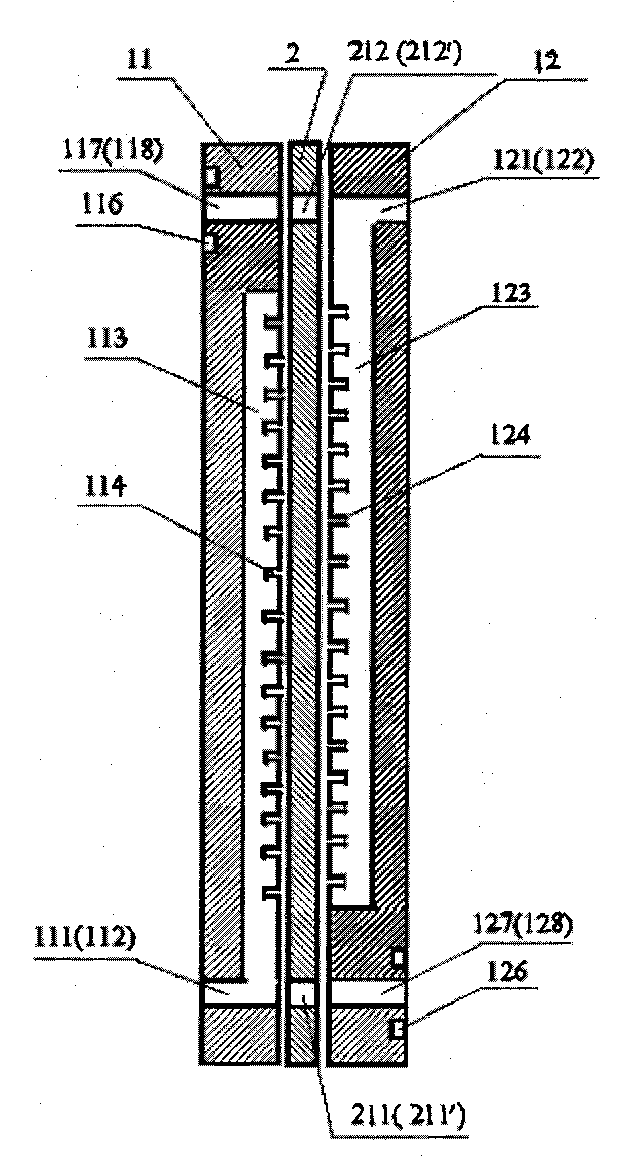
[0093] The structure of the bipolar plate frame and stack of the flow battery according to the present invention is further described as follows.
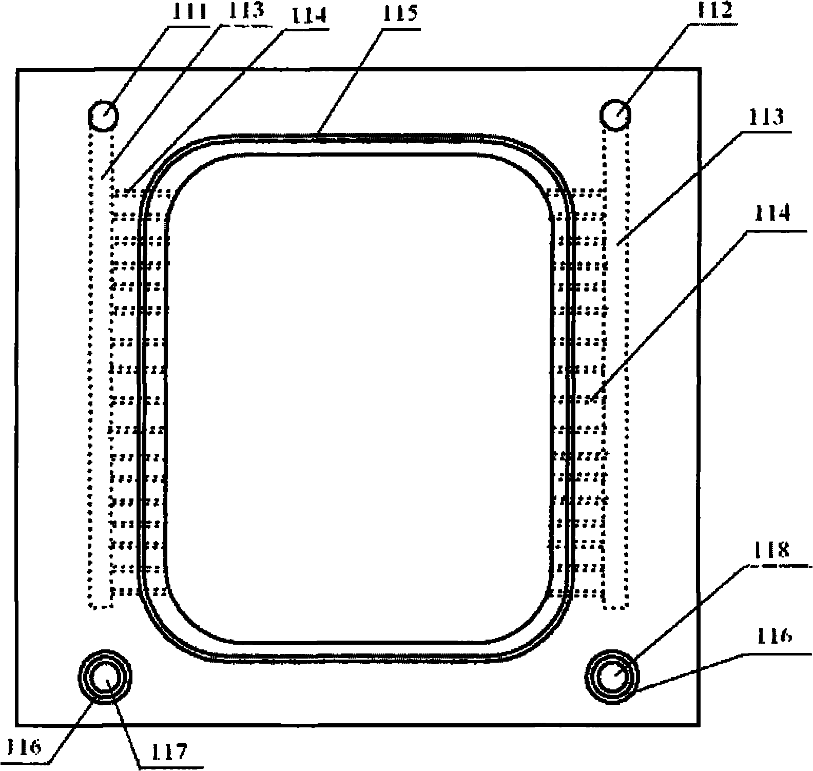
[0094] Upper electrode frame (11): The material is polyvinyl chloride, the length is 200 mm, the width is 200 mm, the thickness is 5 mm, the sealing groove is 3 mm wide, and the depth is 1.6 mm. The diameter of the first O-ring (115A) is 146 mm. Wire diameter 2.65 mm.
[0095] Bipolar plates (2): liquid-impermeable graphite, length 200 mm, width 200 mm, thickness 4 mm
[0096] The lower electrode frame (12): the material is polyvinyl chloride, the length is 200 mm, the width is 200 mm, the thickness is 5 mm, the sealing groove is 3 mm wide, and the depth is 1.6 mm. The diameter of the second O-ring (125A) is 132 mm. Wire diameter 2.65 mm.
[0097] The upper electrode frame, the lower electrode frame, and the liquid-impermeable graphite were bonded using polyvinyl chloride plastic adhesive. The bonded bipolar plate frame is used ...
Embodiment 2
[0103]The bipolar frame structure of the flow battery according to the present invention is further described as follows.
[0104] Upper electrode frame (11): material is polyvinylidene fluoride, length 850 mm, width 450 mm, thickness 4 mm, the first sealing groove (115) is 3 mm wide and 1.6 mm deep.
[0105] Bipolar plate (2): a bipolar plate made of conductive plastic, with a length of 850 mm, a width of 450 mm, a thickness of 2 mm, and a conductivity greater than 45 S / cm.
[0106] Lower electrode frame: the material is polyvinylidene fluoride, the length is 850 mm, the width is 450 mm, and the thickness is 4 mm. The second sealing groove (125) is 3 mm wide and 1.6 mm deep.
[0107] The upper electrode frame (11), the lower electrode frame (12) and the bipolar plate (2) made of conductive plastic are welded, and the integrated bipolar plate frame is used as a part.
[0108] O-ring C (7): use a neoprene O-ring with a wire diameter of 2.65 and a diameter of 18 mm for sealing....
PUM
| Property | Measurement | Unit |
|---|---|---|
| length | aaaaa | aaaaa |
| depth | aaaaa | aaaaa |
| diameter | aaaaa | aaaaa |
Abstract
Description
Claims
Application Information
 - R&D Engineer
- R&D Manager
- IP Professional
- Industry Leading Data Capabilities
- Powerful AI technology
- Patent DNA Extraction
Browse by: Latest US Patents, China's latest patents, Technical Efficacy Thesaurus, Application Domain, Technology Topic, Popular Technical Reports.
© 2024 PatSnap. All rights reserved.Legal|Privacy policy|Modern Slavery Act Transparency Statement|Sitemap|About US| Contact US: help@patsnap.com