Microwave plasma ignition device

A technology of microwave plasma and igniter, which is applied in the direction of plasma, combustion ignition, combustion method, etc., can solve the problem that the microwave plasma igniter cannot be used for a long time, and achieve the effect of full effect and high conversion efficiency

Inactive Publication Date: 2010-10-06
白野 +1
View PDF4 Cites 16 Cited by
  • Summary
  • Abstract
  • Description
  • Claims
  • Application Information

AI Technical Summary

Problems solved by technology

[0006] The purpose of the present invention is to overcome the technical problems and shortcomings that existing microwave plasma igniters cannot be used for a long time, and provide a microwave plasma igniter that can be used for a long time

Method used


Image

  • Microwave plasma ignition device
  • Microwave plasma ignition device
  • Microwave plasma ignition device

Examples


Embodiment

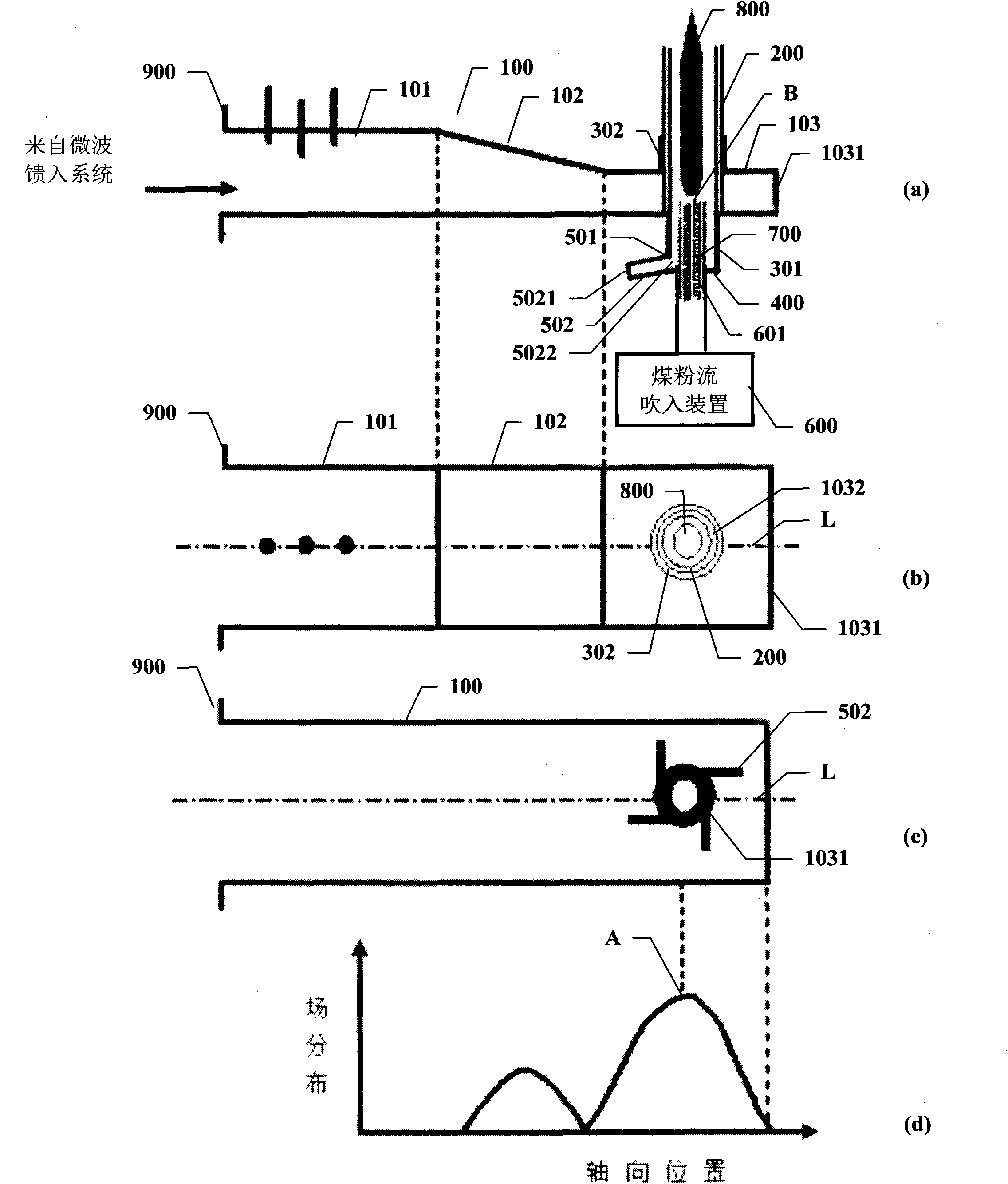
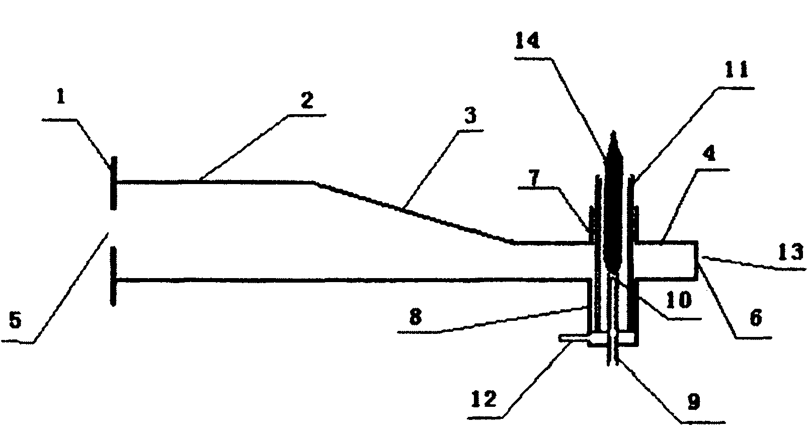
[0022] In this embodiment, as figure 1 As shown in (a), the microwave resonant cavity 100 includes:

[0023] A standard rectangular waveguide 101, the beginning of which is connected to the microwave power feeding system and having an equivalent short-circuit surface forming device; the microwave power feeding system inputs high-power microwaves to the standard rectangular waveguide 101;

[0024] A tapered rectangular waveguide 102, the beginning of which is connected to the end of the standard rectangular waveguide 101; from the beginning to the end of the tapered rectangular waveguide 102, its narrow side is compressed according to a linear law;

[0025] A narrow-side compressed rectangular waveguide 103, the beginning of which is connected to the end of the tapered rectangular waveguide 102, and the height of the narrow side at the end of the tapered rectangular waveguide 102 is the same, and the end is a metal short-circuit plate 1031; the upper and lower sides of the narrow-side...


PUM


Abstract

The invention discloses a microwave plasma ignition device, which comprises a microwave resonance cavity, a quartz glass tube plasma generating area, a tangential air supply device and a coal dust flow blowing-in device. The coal dust flow blowing-in device axially blows coal dust flow into the microwave plasma generating area in a quartz glass tube; when the input microwave power exceeds a critical value, the microwave plasma generating area generates initial ionization under the excitation of micro coal dust in the coal dust flow, and the initial ionization is transited to the whole quartz glass tube through avalanche effect so as to form a microwave plasma torch. Meanwhile, the coal dust flow is ignited to form a coal dust microwave plasma torch and is blown out from the upper end of the quartz glass tube along the axial direction of the quartz glass tube. The coal dust and the microwave plasma are mutually acted so as to raise the temperature of the output torch of the ignition device, increase the ignition, combustion support and combustion stabilization capabilities of the microwave plasma ignition device and meanwhile overcome the defects that the microwave plasma torch is excited by coaxial inner conductors in the microwave plasma generating area and the high-temperature plasma torch melts the coaxial inner conductors due to long time.

Description

Technical field [0001] The invention belongs to the technical field of high-power microwave applications, and relates to a microwave plasma igniter that uses high-power microwaves to generate a plasma torch. Background technique [0002] Microwave plasma is a quasi-balanced plasma with high charge density and temperature generated by electrodeless discharge. Compared with direct current and radio frequency plasma, it has the characteristics of high conversion efficiency, high temperature and large volume. [0003] In the field of microwave industrial applications, relevant international organizations have given two operating frequency windows, namely 915MHz and 2450MHz. In these operating frequency windows, for the excitation of microwave plasma, when the pressure is 1 atmosphere or higher, the microwave field strength to produce discharge needs to be greater than 3×10 4 v / cm, exceeding the microwave field strength required for low-pressure plasma excitation by two orders of magni...

Claims


Application Information

Patent Timeline
Patent Type & Authority Applications(China)
IPC IPC(8): F23Q7/02H05H1/30
CPCF23Q7/02H05H1/30
Inventor 白野蒲力萌
Owner 白野
Why Eureka
Try Eureka