Energy supply system mainly through gas and steam combined cycle cogeneration

An energy supply system and combined cycle technology, applied in the energy field, can solve problems such as unreasonable energy utilization, high energy consumption for cooling transmission and distribution, high pump consumption, etc., and achieve the effect of avoiding transmission and distribution losses, reducing investment and transmission and distribution losses

Active Publication Date: 2010-10-13
TSINGHUA UNIV +1
View PDF5 Cites 43 Cited by
  • Summary
  • Abstract
  • Description
  • Claims
  • Application Information

AI Technical Summary

Problems solved by technology

In particular, distributed energy supply requires base load to determine power generation capacity, and insufficient power can be supplemented by urban power grids, which exacerbates this contradiction
[0005] (2) Energy utilization is unreasonable, and cascade utilization of energy has not been realized
[0006] (3) The integrated utilization of renewable energy and gas cogeneration system is not considered
[0007] (4) High energy consumption for cool...

Method used


Image

  • Energy supply system mainly through gas and steam combined cycle cogeneration
  • Energy supply system mainly through gas and steam combined cycle cogeneration
  • Energy supply system mainly through gas and steam combined cycle cogeneration

Examples


Embodiment 1

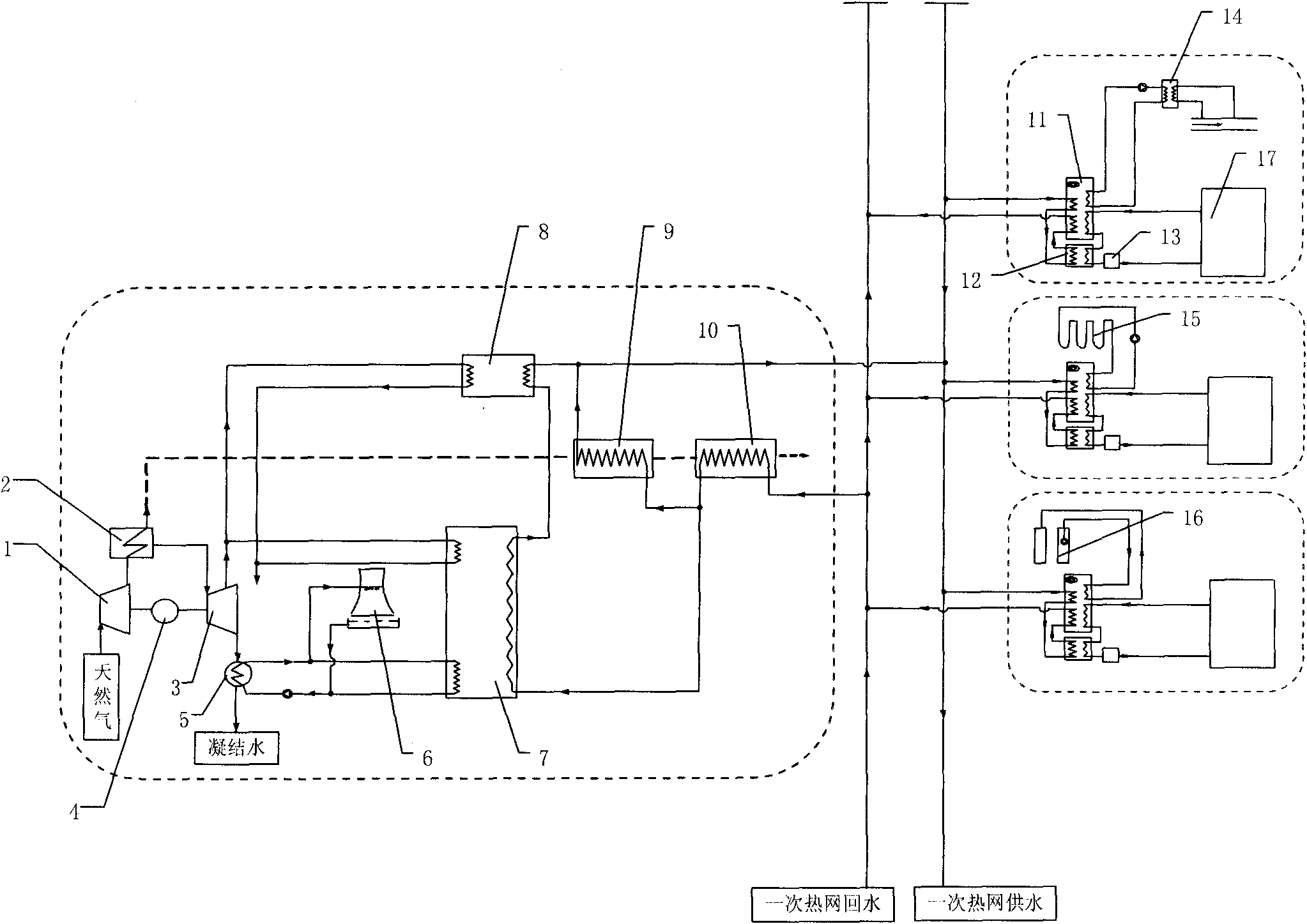
[0033] Figure 1(a) and Figure 1(b) are schematic diagrams of the basic flow charts of heating and cooling for direct recovery of waste heat from flue gas, recovery of waste heat from condensation by steam-type absorption heat pump, and parallel connection of heating side.

[0034] This energy supply mode mainly consists of gas turbine 1, waste heat boiler 2, steam turbine 3, generator 4, condenser 5, cooling tower 6, steam absorption heat pump 7, steam-water heat exchanger 8, high-temperature flue gas exchange Heater 9, flue gas condensing heat exchanger 10, supplementary combustion hot water absorption heat pump 11, water-water heat exchanger 12, gas boiler 13, solution dehumidification air conditioner 18, domestic hot water preheating heat exchanger 19, a No. underground pipe heat exchanger 15 or underground water pumping, recharge well 16 or sewage heat exchanger 14 and connecting pipelines and accessories.

[0035]Under the winter heating conditions shown in Figure 1(a), n...

Embodiment 2

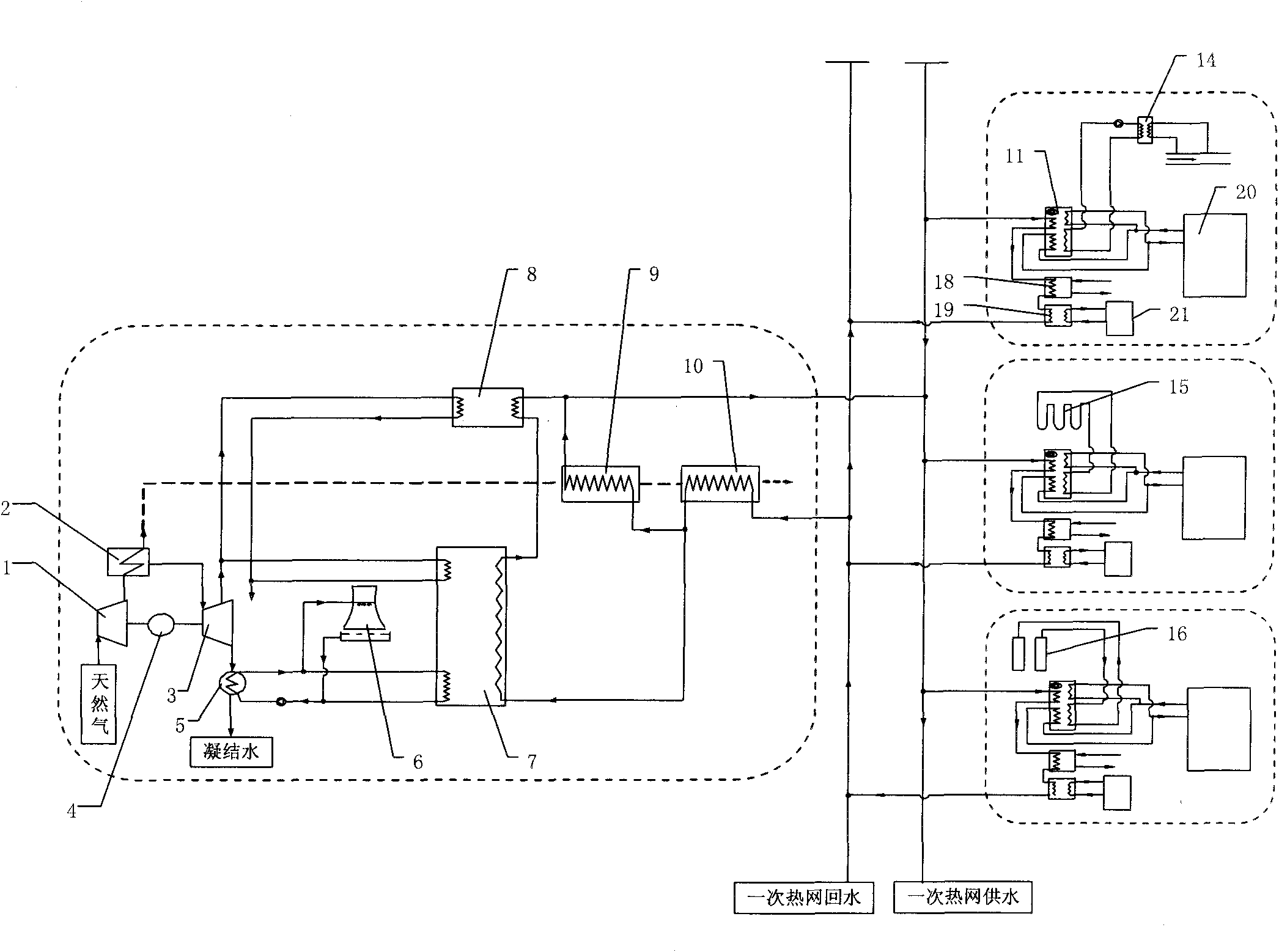
[0038] Fig. 2(a) and Fig. 2(b) are the basic flow diagrams of heating and cooling in direct recovery of condensing waste heat, recovery of low-temperature flue gas waste heat by steam-type absorption heat pump, and parallel connection of heating side, respectively.

[0039] This energy supply mode mainly consists of gas turbine 1, waste heat boiler 2, steam turbine 3, generator 4, condenser 5, steam-type absorption heat pump 7, steam-water heat exchanger 8, high-temperature flue gas heat exchanger 9, Flue gas condensing heat exchanger 10, afterburning hot water absorption heat pump 11, water-water heat exchanger 12, gas boiler 13, solution dehumidification air conditioner 18, domestic hot water preheating heat exchanger 19, No. 1 buried pipe Heat exchanger 15 or underground water pumping, recharge well 16 or sewage heat exchanger 14 and connecting pipelines and accessories.

[0040] Under the winter heating conditions shown in Figure 2(a), the return water of the primary heati...

Embodiment 3

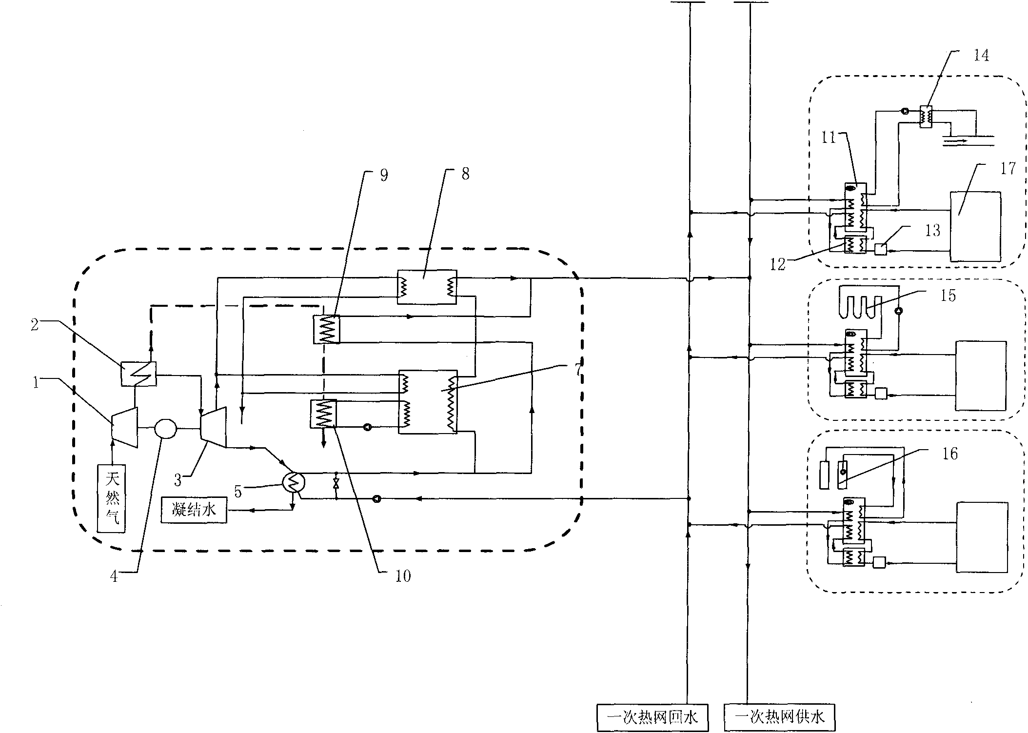
[0043] Figure 3(a) and Figure 3(b) are schematic diagrams of the basic flow charts of heating and cooling for direct recovery of flue gas waste heat, three-stage steam-type absorption heat pump series recovery of condensate waste heat, and parallel connection of the heating side, respectively.

[0044] This energy supply mode mainly consists of gas turbine 1, waste heat boiler 2, steam turbine 3, generator 4, condenser 5, cooling tower 6, primary steam absorption heat pump 7a, secondary steam absorption heat pump 7b, three Stage steam absorption heat pump 7c, steam-water heat exchanger 8, high-temperature flue gas heat exchanger 9, flue gas condensation heat exchanger 10, supplementary combustion hot water absorption heat pump 11, water-water heat exchanger 12, Composed of gas boiler 13, solution dehumidification air conditioner 18, domestic hot water preheating heat exchanger 19, No. 1 buried pipe heat exchanger 15 or groundwater pumping, recharge well 16 or sewage heat exchan...


PUM


Abstract

The invention relates to an energy supply system mainly through gas and steam combined cycle cogeneration, and belongs to the technical field of energy sources. The system adopts a mode of combined heating of a smoke condensing heat exchanger, a condenser, a steam absorption heat pump, a high-temperature smoke heat exchanger and a steam-water heat exchanger on a heat source side; return water of a heat supply network directly recovers low-temperature smoke condensed waste heat, high-temperature smoke waste heat or condensed steam waste heat; and simultaneously, the steam absorption heat pump driven by extracted steam is used for recovering condensed steam discharged heat or partial smoke waste heat. During heat supply in winter, a client uses a supplementary-fired hot water absorption heat pump and a water-water heat exchanger to heat secondary water in the heat supply network for heat supply and extract low-grade heat for heat supply from a superficial layer soil source, an underground water source or a geothermal water source; and in summer, the client uses the hot water absorption heat pump to refrigerate hot water in the heat supply network and a liquid desiccant air conditioner to remove humidify and preheat domestic hot water. Compared with the conventional system, the system of the invention has good economy and application prospect; and the energy utilization rate of the system is greatly improved.

Description

technical field [0001] The invention proposes a new energy supply system based on gas-steam combined cycle heat and power cogeneration, which belongs to the field of energy technology. Background technique [0002] Gas cogeneration is a form of energy utilization in which heat and electricity are produced simultaneously. It uses high-grade thermal energy for power generation and low-grade thermal energy for heating, which not only improves energy utilization efficiency, but also reduces environmental pollution. Natural gas is a clean energy with high calorific value. It produces far less greenhouse gas and other harmful substances than other fossil energy sources when burned. In particular, natural gas combined heat and power has great potential in reducing carbon and air pollution emissions. The combined heat, power and cooling energy system developed on the basis of mature technologies such as combined heat and power, centralized heating and cooling, has attracted increas...

Claims


Application Information

Patent Timeline
IPC IPC(8): F01K17/02F02C6/04F01K11/02F25B29/00
CPCY02B30/123Y02B30/52Y02E20/14
Inventor 付林李永红赵玺灵张世钢罗勇
Owner TSINGHUA UNIV
Why Eureka
Try Eureka