Biomass high-temperature flue gas gasification combination coal burning boiler and low-pollution combustion method thereof

A coal-fired boiler and high-temperature flue gas technology, applied in the field of coal-fired boilers, can solve the problems of high emission concentration, lower boiler output, lower ash melting point, etc., and achieve the effects of reducing NOX concentration, reducing tar content, and reducing slagging tendency

Active Publication Date: 2010-10-20
ZHEJIANG GUANGHAN ENVIRONMENTAL PROTECTION TECH
View PDF4 Cites 41 Cited by
  • Summary
  • Abstract
  • Description
  • Claims
  • Application Information

AI Technical Summary

Problems solved by technology

But it may reduce boiler output, limit the type and proportion of biomass used
After all, pulverized coal and biomass are two fuels with different physical properties. Their ignition temperature, combustion time, and flow trajectory in the air are all different. The unified combustion after mixing is prone to combustion instability, flame center changes, and combustion efficiency. drop and other issues
Moreover, biomass is rich in alkali metals. After mixed combustion, due to the presence of alkali metals, the ash melting point decreases and sintered ash deposits increase, resulting in slagging tendencies on heating surfaces such as boiler water wall superheaters and reheaters and high-temperature corrosion tendencies of alkali metals. enhanced, and the corrosion problem of HCl is also very serious
NO in the exhaust flue gas under this combustion mode X higher concentrations of emissions

Method used


Image

  • Biomass high-temperature flue gas gasification combination coal burning boiler and low-pollution combustion method thereof
  • Biomass high-temperature flue gas gasification combination coal burning boiler and low-pollution combustion method thereof
  • Biomass high-temperature flue gas gasification combination coal burning boiler and low-pollution combustion method thereof

Examples


Embodiment Construction

[0028] The present invention provides a biomass high-temperature flue gas gasification combined coal-fired boiler and its low-pollution combustion method. The present invention will be further described below in conjunction with the accompanying drawings and specific implementation methods.

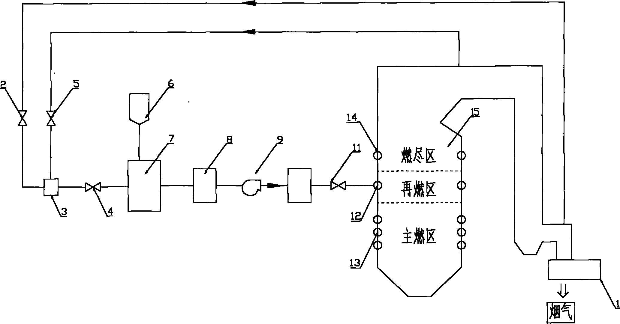
[0029] Such as figure 1As shown, the furnace outlet of the coal-fired boiler 15 leads to a high-temperature flue gas pipe, and the air preheater 1 of the coal-fired boiler 15 leads to a low-temperature flue gas pipe before the flue gas inlet, and the two flue gas pipes are jointly connected to the flue gas mixer 3 , the flue gas mixer 3 is sequentially connected with the gasifier 7, the gas purification chamber 8, the booster fan 9, and the gas storage tank 10, and finally passes into the reburning zone of the coal-fired boiler 15; the gasifier 7 is connected with a biomass bin 6. A low-temperature flue gas damper 2 is set between the coal-fired boiler 15 and the flue gas mixer 3, a high...


PUM


Abstract

The invention belongs to the technical field of a coal burning boiler and particularly relates to a biomass high-temperature flue gas gasification combination coal burning boiler and a low-pollution combustion method thereof. Flue gas serving as a gasification agent enters a gasification furnace; a biomass to be gasified in a biomass bin also enters the gasification furnace; gasified biomass fuel gas enters a fuel gas purification chamber to be subjected to primary purification to remove H2S, HCl and oil tar impurities; after a pressure head of the purified biomass fuel gas is improved by a booster fan, the purified biomass fuel gas enters a fuel gas storage tank and then enters a hearth of the coal burning boiler by a fuel gas nozzle to be burnt; the content of the biomass in the total glue gas is in the range of 0 to 30 percent and the whole system can still operate stably. The use of the biomass effectively reduces discharge of CO2 and SO2. The high-temperature flue gas is used as a heat source to gasify the biomass so as to reduce the content of the oil tar in the biomass fuel gas. The generated biomass fuel gas has high CO2 concentration. The reducing effect of the fuel gas on NOX is far superior to that of the biomass solid on NOX. The NOX concentration is effectively reduced.

Description

technical field [0001] The invention belongs to the technical field of coal-fired boilers, and in particular relates to a biomass high-temperature flue gas gasification combined coal-fired boiler and a low-pollution combustion method thereof. Background technique [0002] Flue gas from coal-fired power plants is rich in CO 2 , SO 2 , NO X , CO 2 is the main greenhouse gas, and the extensive use of fossil fuels emits a large amount of CO 2 cause the Earth's temperature to rise, SO 2 and NO X Entering the atmosphere, causing acid rain and photochemical pollution, seriously damaging the ecological environment. Pulverized coal boiler units with a unit capacity of less than 100MW are facing policy pressure to be forced to close due to poor economy and large pollutant emissions. And biomass fuel due to its zero CO 2 emissions, SO 2 and NO X The emission is very low. As a renewable new energy source, the utilization of biomass fuel is being supported by policies. Biomass ...

Claims


Application Information

Patent Timeline
Patent Type & Authority Applications(China)
IPC IPC(8): F22B31/00F23C1/12F23C5/08C10J3/14
CPCY02P20/129
Inventor 叶力平翁卫国
Owner ZHEJIANG GUANGHAN ENVIRONMENTAL PROTECTION TECH
Why Eureka
Try Eureka