Long-distance waste heat recovery system of drying tail gas

A waste heat recovery system and a technology for drying tail gas, applied in drying solid materials, drying, waste heat treatment, etc., can solve the problems of large consumption of drying medium, high attenuation rate of heat transfer, large power consumption of heat-carrying medium, etc. Good temperature uniformity, good heat transfer effect and small footprint

Active Publication Date: 2010-10-20
SHAN DONG TIAN LI DRYING EQUIP
View PDF1 Cites 9 Cited by
  • Summary
  • Abstract
  • Description
  • Claims
  • Application Information

AI Technical Summary

Problems solved by technology

[0003] In the hot air and superheated steam drying process, the waste heat of the drying exhaust gas is recovered and the new drying medium is heated. However, in some drying processes such as tunnel kiln drying and spray drying, the distance between the exhaust gas discharge point of the dryer and the fresh air access point is tens of meters or even higher. 100 meters, the distance between the waste heat discharge point and the heat demand node is relatively long, because this drying process consumes a lot of drying media, for example, the amount of hot air in some drying processes can reach 50,000 to 100,000 m 3 / h, if the ordinary waste heat recovery process is adopted, a bulky pipeline transportation system needs to be set up, and at the same time, the power consumption of transporting the heat-carrying medium is large, and the special conditions of some dry sites are not suitable for installing such a large-scale Pipeline transportation system; if the extended type oscillating flow heat pipe heat exchanger is used, the heat transfer attenuation rate is high, the heat exchanger consumes a lot of steel, and the initial investment is high, so this part of the waste heat has not been fully recovered

Method used


Image

  • Long-distance waste heat recovery system of drying tail gas
  • Long-distance waste heat recovery system of drying tail gas

Examples


Embodiment Construction

[0016] The present invention will be further described below in conjunction with the accompanying drawings.

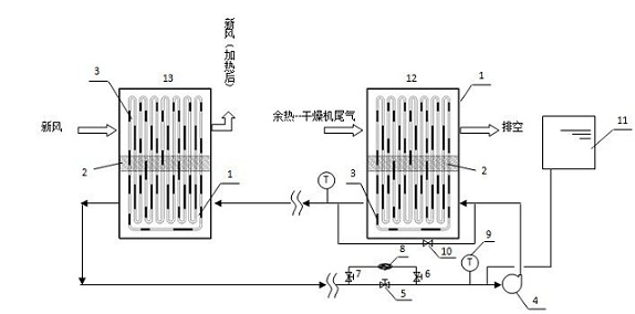
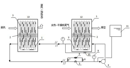
[0017] The waste heat of the exhaust gas of the dryer first flows through the evaporating section 1 of the primary oscillating flow heat pipe 12, and the heat is transferred to the condensing section 3 at the other end of the adiabatic section 2 through the pulsating heat pipe. Transfer to the heat transfer oil, after the heat transfer oil is warmed up, it is transported to the evaporation section 1 of the secondary oscillating flow heat pipe 13 through a long distance under the action of the circulation pump 4, and the heat released by the heat transfer oil is transferred to the condensation section of the secondary oscillating flow heat pipe 13 through the pulsating heat pipe 3. The heat pipe in the condensing section 3 transfers heat to the fresh air, and the heated fresh air returns to the drying process to realize waste heat recovery and reuse in this system.

[0...


PUM


Abstract

The invention relates to a long-distance waste heat recovery system of drying tail gas, which can effectively recover the waste heat of drier tail gas and transmit heat to a required node to preheat fresh air with lower energy consumption, and the preheated fresh air returns to a drying system to dry the material, therefore, the waste heat recycle is realized. The long-distance waste heat recovery system comprises a drying equipment tail gas heat source, wherein the heat source is connected with at least one first-level oscillatory flow heat pipe, the oscillatory flow heat pipe heats a heat carrier in a long-distance conveyer device, a plurality of second-level oscillatory flow heat pipes for acquiring heat energy are arranged on the long-distance conveyer device, and a control device is arranged on the long-distance conveyer device.

Description

technical field [0001] The invention relates to a long-distance waste heat recovery technology, and is especially suitable for a long-distance drying tail gas waste heat recovery system which is suitable for long-distance drying tail gas waste heat recovery after long-distance transportation. Background technique [0002] At present, almost all industries are inseparable from drying operations. Drying is a relatively large unit of industrial energy consumption. 14% of industrial energy consumption in developed countries is used for drying. In some industries, drying energy consumption even accounts for 10% of production energy consumption. 35%. The tail gas of the drying equipment carries a large amount of waste heat. Therefore, it is an inevitable trend for the innovation and development of drying operations to effectively use energy and reduce adverse effects on the environment. [0003] In the hot air and superheated steam drying process, the waste heat of the drying exh...

Claims


Application Information

Patent Timeline
IPC IPC(8): F28D15/02F28D15/06F26B25/00F27D17/00
CPCY02P70/10
Inventor 李选友耿文广张文克罗光亮高玲
Owner SHAN DONG TIAN LI DRYING EQUIP
Why Eureka
Try Eureka