Safety syringe

A safety syringe and syringe technology, which is applied in the field of medical devices, can solve the problems such as the inability of the needle tip to be fixed, non-compliant, unsafe hidden dangers, etc., and achieve the effects of avoiding infection and disease transmission, easy to accept use, and reliable safety protection.

Inactive Publication Date: 2010-10-27
张亚平
View PDF2 Cites 9 Cited by
  • Summary
  • Abstract
  • Description
  • Claims
  • Application Information

AI Technical Summary

Problems solved by technology

[0005] 1. Manually pulling back the needle requires both hands. During the operation, there is a risk of stabbing yourself, which does not meet the modern prevention norms and requirements: in the process of realizing the safety protection of the syringe, only one-handed operation is allowed.
[0006] 2. The method of automatically recovering the injection needle by the spring: the structure where the spring is located at the needle seat (the mainstream solution at home and abroad) makes the recovery device and the needle seat an integrated structure. Once the syringe leaves the factory, the needle cannot be replaced again. In the clinical use environment Different injection needles have different requirements, which brings inconvenience to users; moreover, since the needle tube is fixed in the needle seat once during the production process, the needle seat is randomly installed in the spring protection device, and the direction of the needle tip edge cannot be changed again. Adjust, after the production is finished, so that the direction of the edge of the needle tip cannot be consistent with the volume scale of the outer cylinder of the syringe (same plane). During clinical operations, especially when the needle is inserted into the blood vessel, the edge of the edge of the medical staff needs to be upward, which is convenient for skin and blood vessels. Once the needle enters the blood vessel, you need to observe the scale line when injecting a certain dose of medicinal liquid. At this time, because the direction of the cutting edge may be opposite to the scale line, you mus...

Method used


Image

  • Safety syringe
  • Safety syringe
  • Safety syringe

Examples


Embodiment Construction

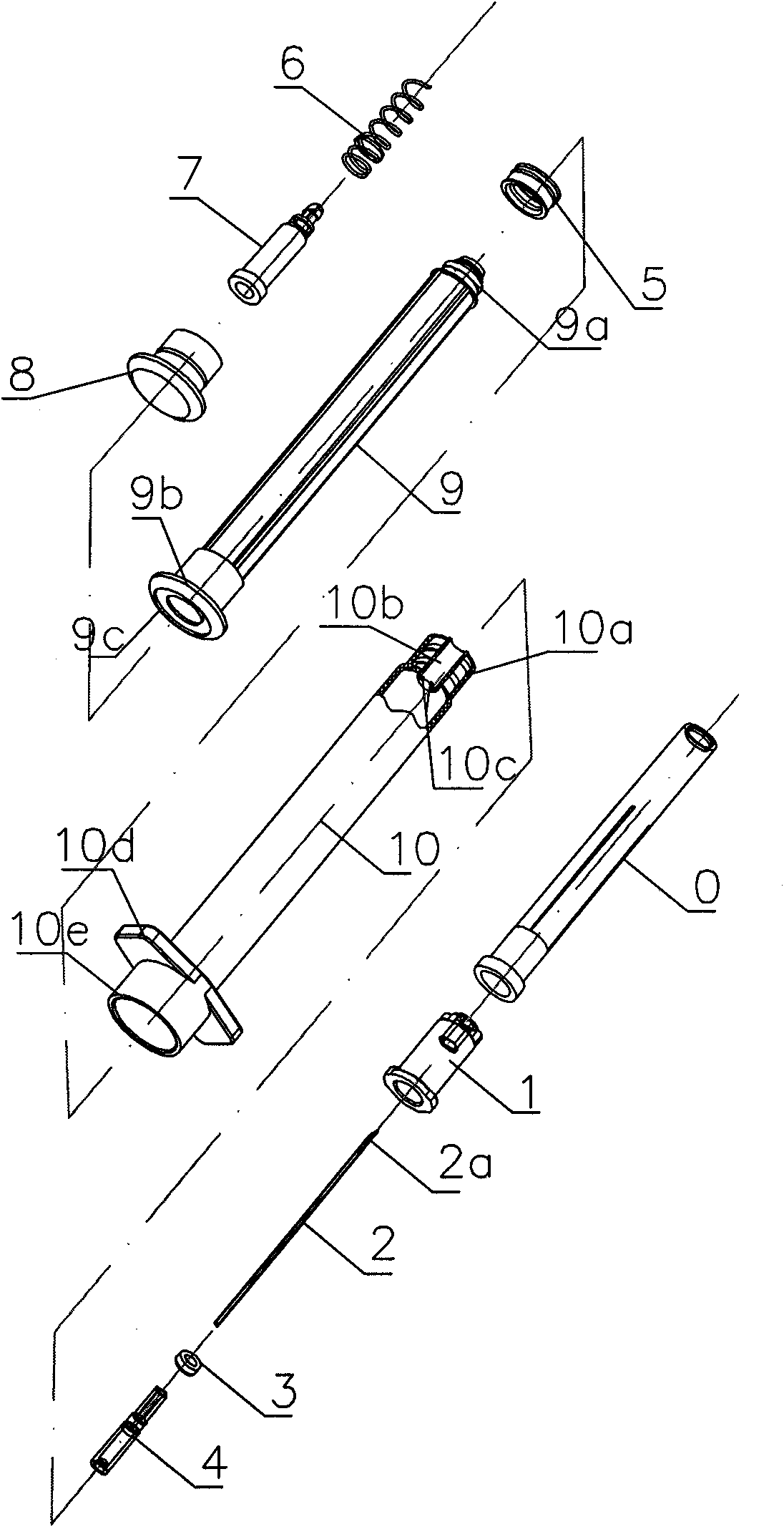
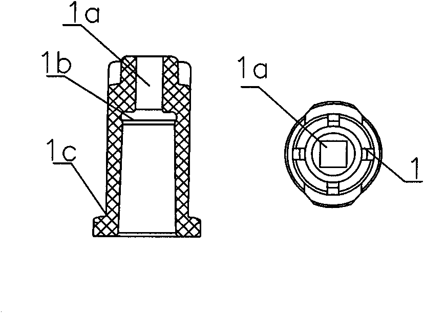
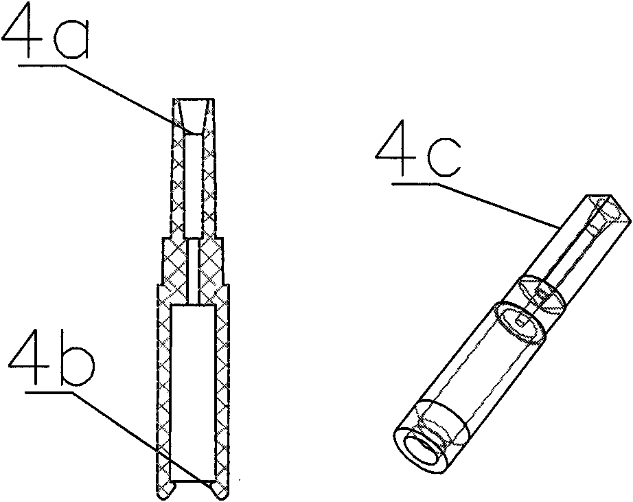
[0027] Depend on figure 1 It can be seen that a safety syringe of the present invention is composed of: needle point sheath 0, outer needle seat 1, needle tube 2, sealing ring 3, inner needle seat 4, piston 5, spring 6, latch 7, end plug 8, push rod 9, The outer cylinder 10 is collectively composed. Sheath 0, outer needle hub 1, needle tube 2, sealing ring 3, and inner needle hub 4 are common injection needle components; sheath 0 is usually set on the outer surface of outer needle hub 1 to protect the needle tip from collision damage, and the front end of needle tube 2 has a sharp edge 2a; the sealing ring 3 is made of elastic plastic material, which acts as a friction seal between the inner and outer needle seats; the inner needle seat 4 has a hole in the center, and the needle tube 2 can be bonded in the hole, the lower half of the inner needle seat 4 is hollow, and the lower end There is a ring-shaped protrusion on the inner edge, and the outer edge of the upper half of th...


PUM


Abstract

A medical safety syringe comprises a syringe needle, an automatic recovery assembly, a needle tip cutting edge positioning structure and a syringe, and is characterized in that the tip of one end of a recovery spring extents to enable the outer diameter of a ring to be greater than the inner bore diameter of a push rod; the compressed spring is braked with a plunger latch by the front end of the inner bore of the push rod; a needle head is pulled out after injection; the push rod is pressed again to compress and deform a piston; the ring edge of the front end of the plunger latch cuts the support piece of the inner wall of the central bore of the front end of an outer cylinder, so an inner needle stand is not supported; the expanded part of the front end of the plunger latch and the annular bulge of the inner bore of the inner needle stand are jogged; a pressing force enables the plunger latch to be separated from the limit of the inner central inner bore of the front end of the push rod; the spring is ejected to drive the plunger latch, the inner needle stand and the needle tip to return to the rear end of the inner bore of the push rod to enable the needle tip to be completely shielded; and because the steel wire tip of the spring, near the needle tip, extents and the spring moves to the needle tip, the steel wire tip can be embedded into the side wall of the inner bore of the push rod to brake the plunger latch, and the syringe needle tip is limited to not emerge. The upper half part of the inner needle stand is a square body; the front end of an outer needle stand is provided with a square bore, and the square body and the square bore form the needle tip cutting edge positioning structure. By the separate structure of the needle stands and the automatic recovery assembly, the syringe can replace the syringe needle according to demands before being used. The characteristics bring convenience for clinical application, so the syringe is easy to popularize.

Description

technical field [0001] The invention relates to a medical instrument, in particular to a medical safety injector used in the tissue puncture process and drug delivery or tissue sample extraction after the puncture. Background technique [0002] Since the emergence of plastic disposable sterile syringes in the 1940s, due to technical (structural) reasons, the product can be reused, which has brought about a large number of blood-borne diseases, especially AIDS, hepatitis C, and hepatitis B. Serious; in 1994, the World Health Organization (WHO) advocated the use of "single-use self-destructing syringes", and technicians and companies have done a lot of exploration on how to prevent and prohibit the reuse of syringes; however, due to blood-borne diseases The root cause of the spread is the re-stabbing of medical staff and patients (cross-use injection needles) by injection needles during the medical process, not the syringe itself; therefore, WHO re-proposed in 1998: "Single-us...

Claims


Application Information

Patent Timeline
IPC IPC(8): A61M5/178A61M5/32A61M5/315A61M5/50A61B10/00
Inventor 张亚平
Owner 张亚平
Why Eureka
Try Eureka