

Flash evaporation feed type internal heat integration energy-saving rectifying device and method
A technology of heat integration and rectification, applied in the field of rectification, which can solve the problems affecting the normal operation and service life of compressors, the negative impact on process safety and smooth operation, and the failure of heat load to be recovered and utilized, etc., to achieve broad industrial application prospects , Reduce operating costs, and save operating costs
- Summary
- Abstract
- Description
- Claims
- Application Information
AI Technical Summary
Problems solved by technology
Method used
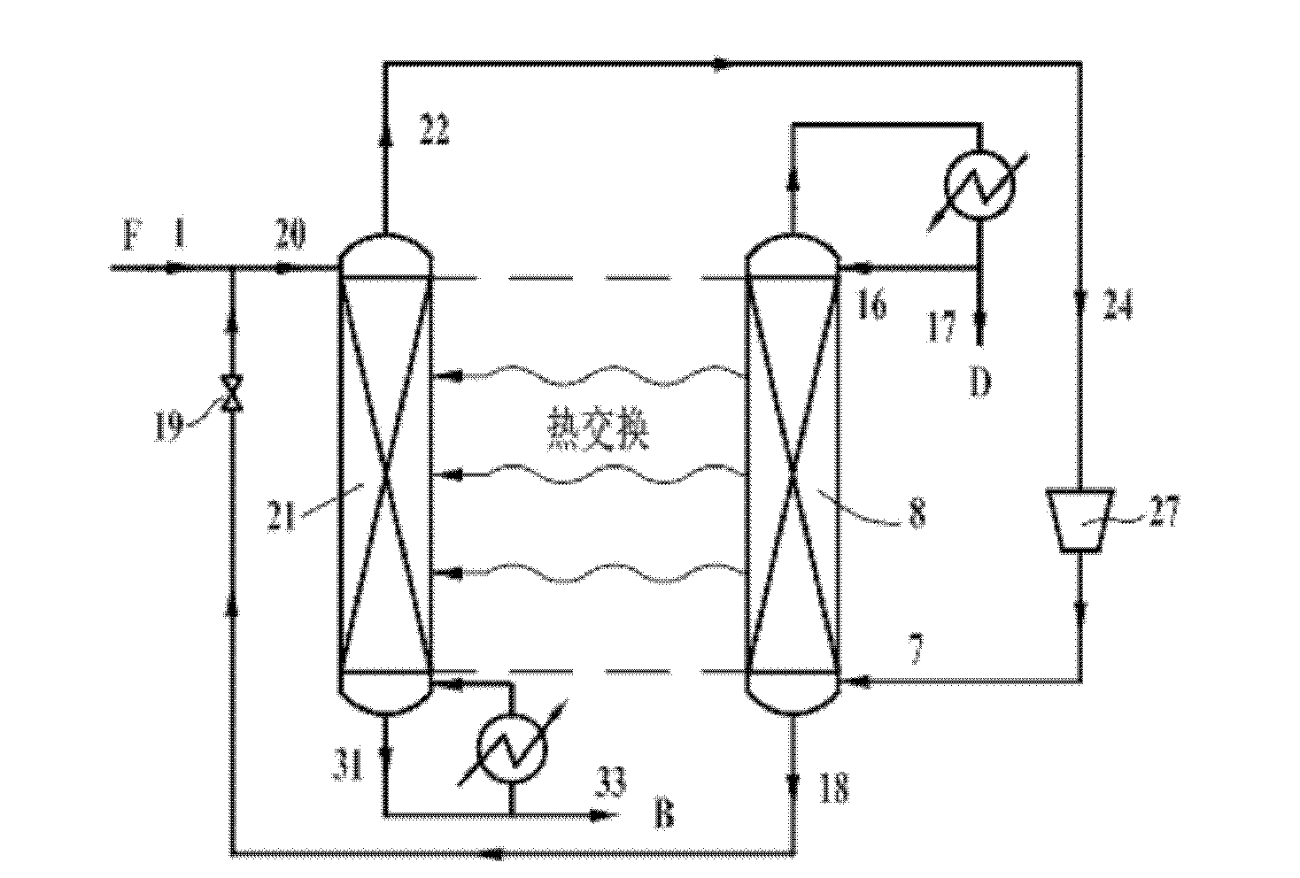
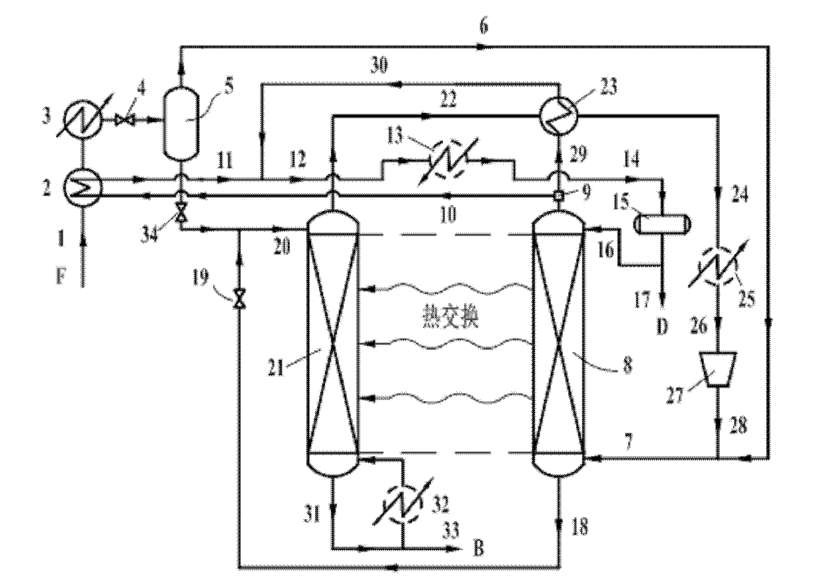
Image

Examples
Embodiment 1
[0036] Embodiment one (typical non-ideal system separation)
[0037] Situation 1: Separation of ethanol-water system, using the process described in the present invention. The feed position is the top of the stripping section, the feed amount is 1000kg / h, the feed composition is 50% (wt%), and the feed temperature is 20°C. The number of theoretical plates in the rectification section and the stripping section is 36, and the feeding position is the top of the stripping section. The operating pressure of the stripping section is normal pressure, and the operating pressure of the rectifying section is 2.5atm. The output of the overhead product in the rectification section is 500kg / h, and the purity of ethanol in the extracted product is controlled above 92% (wt%). In this case, the heat load provided by condensation at the top of the rectification section is greater than the sum of the heat load required by the system heat recovery heat exchanger and the gas superheater, and th...
Embodiment 2
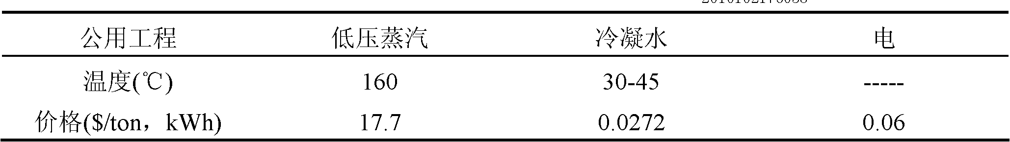
[0061] Comparing the calculation results of Table 4 and Table 5, it can be seen that the annual total operating cost of Example 1, Situation 2 is 45315.51$ / y, while the common internal heat integrated rectification tower used for comparison with Embodiment 1, Situation 2 Total annual operating expenses are $67121.69 / y. Therefore, the total annual operating cost of Embodiment 1, Case 2 using the technology and device of the present invention is saved by 32.49%. Embodiment two (typical ideal system separation)
[0062] Situation 1: The method of the present invention is used for the separation of benzene-toluene system, and the process described in the present invention is adopted. The feed position is the top of the stripping section, the feed amount is 1000kg / h, the feed composition is 50% (wt%), and the feed temperature is 0°C. The number of theoretical plates in the rectification section and the stripping section is 34, and the feeding position is the top of the stripping ...
PUM
 Abstract
Description
Claims
Application Information