
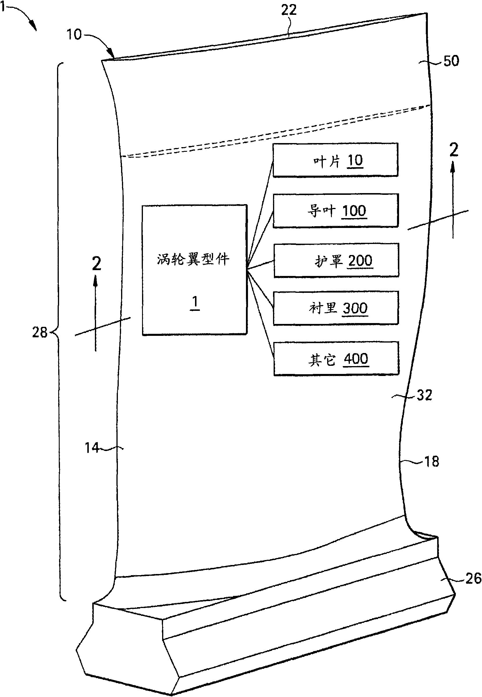
Erosion and corrosion resistant turbine compressor airfoil and method of making the same

A technology of turbo compressors, airfoils, applied in the direction of components, pump elements, mechanical equipment, etc. of pumping devices for elastic fluids

Inactive Publication Date: 2010-11-03
GENERAL ELECTRIC CO
View PDF8 Cites 29 Cited by
  • Summary
  • Abstract
  • Description
  • Claims
  • Application Information

AI Technical Summary

Problems solved by technology

[0005] While various approaches to improving the erosion or corrosion resistance of stainless steel turbocompressor airfoils have been proposed, there remains a need for stainless steel turbocompressor airfoils with improved erosion and corrosion resistance

Method used


Image

  • Erosion and corrosion resistant turbine compressor airfoil and method of making the same
  • Erosion and corrosion resistant turbine compressor airfoil and method of making the same
  • Erosion and corrosion resistant turbine compressor airfoil and method of making the same

Examples


example 1

[0072] A water drop erosion test is used to simulate water impact on compressor components in a turbine during water washout and water jet power increase. Control particle velocity and droplet size to best reproduce the turbo environment. A series of cylindrical test specimens of Custom 450 stainless steel were coated with several corrosion-resistant coatings including a single layer of TiN with a thickness of approximately 6 to 8 microns, multiple layers of Ti and TiN each with a thickness of 5 microns. minimum thickness and have a total thickness of about 45 microns, and a WC-CoCr layer having a composition by weight of 10% Co, 4% Cr and balance WC and a thickness of about 4-6 mils. Test coupons with these erosion-resistant coatings were subjected to testing in a rotating test fixture, where the test coupons were attached to the outboard end of the leading edge of a motor-driven five-root blade. The apparatus was designed to rotate the blade and test specimen at 800 feet pe...

example 2

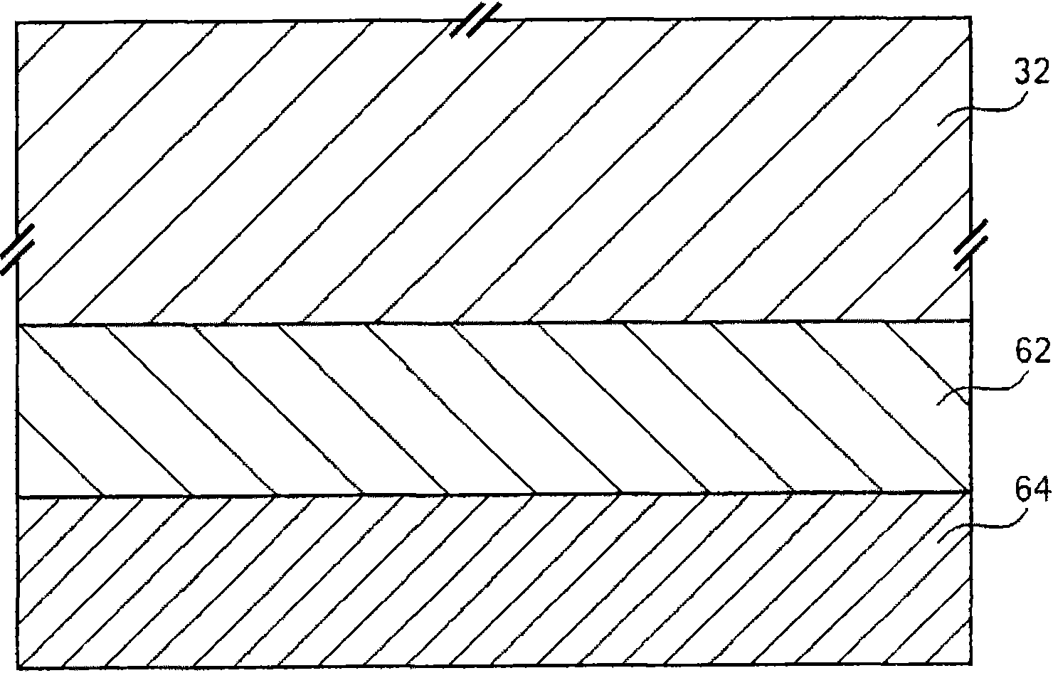
[0074] In a second test, polarization sweep and galvanic corrosion tests were performed on Custom 450 test coupons coated with the airfoil coating described herein. A series of Custom 450 stainless steel test specimens were coated with an airfoil coating, which consisted of a sheet of Custom 450 as the airfoil surface, a 50-micron thick Al coating deposited by an air plasma spray (APS) process, and an 150 μm thick WC-CoCr coating deposited by fuel (HVOF) spraying process. Test conditions included 5% NaCl (similar to salt spray chloride levels), which is acidic, pH = 4.0 at 50 degrees Celsius, to simulate condensing gas with moisture and salt. The test is an accelerated corrosion test used to evaluate coating performance. Cyclic Polarization Corrosion Testing was utilized according to ASTM G61 for the creviced Custom 450 coupons. The test specimens were gapped using ceramic washers torqued down to 40 foot-pounds by the associated bolts. Such as Figure 9 As shown, hysteresi...


PUM

PropertyMeasurementUnit
thicknessaaaaaaaaaa
thicknessaaaaaaaaaa
thicknessaaaaaaaaaa

Abstract

The invention relates to an erosion and corrosion resistant turbine compressor airfoil and a method of making the same. A sacrificial and erosion-resistant turbine compressor airfoil includes a turbine compressor airfoil having a modified airfoil surface. The airfoil surface has an airfoil coating that includes a sacrificial coating comprising a layer of Al, Cr, Zn, an Ni-Al alloy, an Al-Si alloy, an Al-based alloy, a Cr-based alloy or a Zn-based alloy, an Al polymer composite, or a combination thereof, or a layer of a conductive undercoat and an overcoat of an inorganic matrix binder having a plurality of ceramic particles and conductive particles embedded therein disposed on the undercoat. The airfoil coating also includes an sacrificial coating, wherein one of the sacrificial coating or the erosion-resistant coating is disposed on the airfoil surface and the other of the corrosion-resistant coating or the erosion-resistant coating is disposed on the respective one, and wherein the sacrificial coating is more anodic than the airfoil surface or the erosion-resistant coating.

Description

technical field [0001] The subject matter disclosed herein relates to turbocompressor airfoils, including turbocompressor airfoils having improved corrosion and erosion resistance, and the manufacture of these turbocompressor airfoils Methods. More particularly, the present invention relates to a turbocompressor airfoil having a turbocompressor airfoil coating that provides improved corrosion and erosion resistance, and the manufacture of a coated turbocompressor Airfoil method. Background technique [0002] Stainless steel turbo compressor airfoils, such as those used in compressors for industrial gas turbines, exhibit spots on the airfoil surface that are susceptible to erosion and corrosion by water droplets. These are believed to be related to various electrochemical dissolution processes resulting from the impact of water droplets and other chemical species present in the droplets, aspirated air, or both. Electrochemically induced corrosion and erosion phenomena that...

Claims


Application Information

Patent Timeline
Patent Type & Authority Applications(China)
IPC IPC(8): F04D29/38F04D29/02
CPCF04D29/324C23C4/06C23C28/345C23C28/00F04D29/023C23C28/322C23C28/324C23C28/3455C23C28/3225C23C28/042C23C28/34C23C28/321C23C28/42C23C30/00C23C28/341F05D2260/95F05D2300/611F05D2230/31
Inventor J·M·利普金K·阿南德D·V·布奇刘煜照S·帕布拉V·K·帕里克J·C·谢费尔G·森达拉拉延
Owner GENERAL ELECTRIC CO
Learn More